Cart
Your shopping cart is empty!
It's never too late to make things right :)


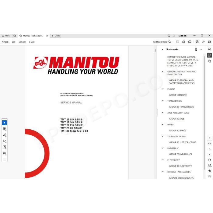
Manitou Truck Mounted Forklift TMT 25 / TMT 27 ST5 Series 1 pdf service & repair manual + operator manual
Models covered:
TMT 25 S K ST5 S1
TMT 27 S K ST5 S1
TMT 27 P K ST5 S1
TMT 25 I K ST5 S1
TMT 25 S 4W K ST5 S1
MANUAL CONTENT:
GENERAL AND SAFETY CHARACTERISTICS
FOREWORD
LIST OF ABBREVIATIONS
WORK DURING THE WARRANTY PERIOD
MAINTENANCE RULES
EXPLANATION OF SYMBOLS
MAINTENANCE POSITION
LIST OF SUPPLIER DOCUMENTATION
CHARACTERISTICS AND SPECIFICATIONS
Weights and forces
Dimensions TMT 25 S K ST5 S1
Dimensions TMT 27 S K ST5 S1
Dimensions TMT 27 P K ST5 S1
Dimensions TMT 25 I K ST5 S1
Dimensions TMT 25 S 4W K ST5 S1
Lubricants and fuels
Lubricants and fuels
LOCATION
Name and identification plates
CONTROL AND ADJUSTMENT
Standard tightening torques
Metric - imperial unit conversion
ENGINE
CHARACTERISTICS AND SPECIFICATIONS
Engine specifications D1803-CR-TE5
LOCATION
Location of engine components - TMT ST5
REMOVAL
Preparation and safety instructions
Remove the engine - TMT ST5
Remove the cooling radiator
REFIT
Refit the components (TMT ST5 S1) (TMT HT & XT)
TRANSMISSION
FLOW DIAGRAMS AND SCHEMATIC DIAGRAMS
Schematic diagram for hydrostatic transmission - Forward gear
Hydrostatic transmission reverse gear schematic diagram - Reverse
Schematic diagram for hydrostatic transmission - Forward - 4-WAY
Hydrostatic transmission schematic diagram - Reverse - 4-WAY
LOCATION
Key to hydrostatic components
Key to steering components
CONTROL AND ADJUSTMENT
Hydrostatic pump adjustment prerequisites
Location of the hydrostatic transmission pump pressure connectors
Transmission A4VG40 hydrostatic pump pressure values
Adjusting the hydrostatic pump traction force
Adjusting the hydrostatic pump for lift truck travel
Hydrostatic transmission adjustment sheet — A4VG-DA
Tow the lift truck
Hydrostatic pump tightening torques
Flow divider tightening torques
4-Way steering selection block tightening torques
Rear wheel motor screw tightening torques
Front wheel motor screw tightening torques
REMOVAL
Remove the hydrostatic pump
Removing the steering block
Removing the front wheel motor
Remove the front wheel motor - 4-Way
Remove the rear wheel motor
Remove the rear steering cylinder
Removing the 4-Way front steering cylinder
Removing the 4-Way steering mode selection unit BSD
Removing the 4-Way INV HP shuttle unit
SPECIFIC TOOLING
Basic manometer box
Digital manometer box
AXLE
CHARACTERISTICS AND SPECIFICATIONS
Pivot characteristics
LOCATION
Location of rear pivot components
Location of front pivot components
REMOVAL
Removing the rear pivot
Removing the front pivot - 4 Way
REFIT
Refitting the rear pivot
BRAKE
LOCATION
Location of the service brake pedal and transmission cut-off components (inching)
CONTROL AND ADJUSTMENT
Adjusting the service brake pedal and transmission cut-off (inching)
Valve TH7 (hydraulic) tightening torque
Hydraulic tightening torques of the steering bloc (orbitrol)
REMOVAL
Remove valve TH7
LIFT STRUCTURE
CHARACTERISTICS AND SPECIFICATIONS
Duplex boom composition
LOCATION
Boom location
CONTROL AND ADJUSTMENT
Preparation and safety instructions
Remove the tilting cylinder
Refit the tilting cylinder
Removing the forks carriage
Refit the forks carriage
Remove the telescopic boom cylinder
Refit the telescopic boom cylinder
Remove the telescope
Refit the telescope
Remove the side shift cylinder
Boom cross sections / slide pad adjustments
REMOVAL
Preparation and safety instructions
Removing the boom
REFIT
Preparation and safety instructions
Refitting the boom
HYDRAULICS
FLOW DIAGRAMS AND SCHEMATIC DIAGRAMS
Hydraulic schematic diagram (TMT 25I ST5 S1)
Hydraulic schematic diagram (TMT 25S 27P 27S ST5 S1)(TMT HT & XT T4)
Hydraulic schematic diagram - 4-WAY
LOCATION
Location of main hydraulic system - steering - telescoping - tilting - lifting - compensation
Location of hydraulic brake system - oil cooling
Location of the "self loading kit" hydraulic circuit – hydraulic track
Location of the folding door hydraulic circuit
CONTROL AND ADJUSTMENT
Purge front steering cylinder - 4 Way
Distributor union tightening torques
Valve bank component tightening torques;
Hydrostatic pump tightening torques
Hydraulic pump tightening torques
Stabilizer valve tightening torques – 4 Way
Folding arms electrovalve tightening torques (option)
REMOVAL
Remove the electrovalve from the folding arms (option)
SPECIFIC TOOLING
Basic manometer box
Digital manometer box
ELECTRICITY
CHARACTERISTICS AND SPECIFICATIONS
E18/S6 electronic module
Fuses and relays
Connectors
FLOW DIAGRAMS AND SCHEMATIC DIAGRAMS
Cable marking on an electrical wiring harness
Electrical diagram by function
LOCATION
2D location of harnesses
3D location of harnesses - (except 4 Way)
2D location of the harness - 4 Way
3D location of harnesses - 4 Way
CONTROL AND ADJUSTMENT
Adjusting the rear pivot sensors
Adjusting the telescoping cut-off
Adjust the boom angular sensor
Checking movement cut-off
Check A: Checking movement cut-off
Check B: Overload check
Testing Overload calibration
TROUBLESHOOTING
Navigate the drivers cab screen menus
Fault and alert screen pages
Troubleshooting on the E18/S6 - 4 Way module
DIAGNOSTIC TOOLS
There are no reviews for this product.