Cart
Your shopping cart is empty!
It's never too late to make things right :)


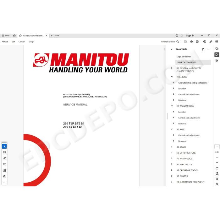
Manitou Telescopic Elevating Work Platform 260 TJP ST5 S1, 280 TJ ST5 S1 pdf service & repair manual
MANUAL CONTENT:
GENERAL AND SAFETY CHARACTERISTICS
FOREWORD
LIST OF ABBREVIATIONS
WORK DURING THE WARRANTY PERIOD
MAINTENANCE POSITION
EXPLANATION OF SYMBOLS
MAINTENANCE RULES
LIST OF SUPPLIER DOCUMENTATION
CHARACTERISTICS AND SPECIFICATIONS
Weights and forces
Lubricants and fuel
Dimensions - 260 TJP ST5 S1
Movement diagram - 260 TJP ST5 S1
Dimensions - 280 TJ ST5 S1
Movement diagram - 280 TJ ST5 S1
LOCATION
Name and identification plates
CONTROL AND ADJUSTMENT
Standard tightening torques
Metric - imperial unit conversion
ENGINE
CHARACTERISTICS AND SPECIFICATIONS
Presentation of the new features of the engine assembly
Specifications of the 4TNV88C-KMU engine
Cooling fan characteristics
LOCATION
Location of engine components
Location of cooling system components
Air system components
Location of fuel system components
CONTROL AND ADJUSTMENT
Regeneration management
Tightening torque for the engine mountings on their silent blocks
REMOVAL
Removing the engine block
TRANSMISSION
LOCATION
Location of hydrostatic components
Location of hydrostatic pump pressure connectors
Location of hydrostatic pump adjustment points
CONTROL AND ADJUSTMENT
Hydrostatic pump adjustment prerequisites
Setting of the low pressure boost valve on the hydrostatic pump
Neutral point adjustment for the servo-control piston of the hydrostatic pump
Setting the DR flow cancellation valve on the hydrostatic pump
Setting of the high pressure valves on the hydrostatic pump
Hydrostatic motor/pump coupling tightening torques
Tightening torque for attaching high pressure hoses to the hydrostatic pump
REMOVAL
Removing the hydrostatic travel motor
Remove the hydrostatic pump
AXLE
CONTROL AND ADJUSTMENT
Putting the machine in freewheel
Reactivate the axle hydrostatic braking system
Axle tightening torques
REMOVAL
Removing the front axle
Removing the rear axle
LIFT STRUCTURE
CHARACTERISTICS AND SPECIFICATIONS
General characteristics of the articulated arm
FLOW DIAGRAMS AND SCHEMATIC DIAGRAMS
Boom kinematics
LOCATION
Location of boom components
CONTROL AND ADJUSTMENT
Speed calibration
Checking boom cable wear
Calibrating telescope travel
Checking reeving cable tension
Checking telescope slide pad clearance
Basket rotation cylinder pin tightening torque
REMOVAL
Preparation and safety instructions
Steps for removing the telescope
Remove the telescope
Steps for removing the telescope components
Removing the telescope components
Remove the basket
Removing the basket overload
Removing the jib
Removing the jib assembly cylinders
Removing the jib hinge
REFIT
Steps for refitting the telescope components
Refitting the telescope components
Steps for refitting the telescope
Reinstall the telescope
HYDRAULICS
FLOW DIAGRAMS AND SCHEMATIC DIAGRAMS
Hydraulic schematic diagram - 260 TJ+ ST5
Hydraulic schematic diagram - 280 TJ ST5
LOCATION
Location of chassis hydraulic components
Location of turntable hydraulic components
Location of boom hydraulic components
Location of the elements of the proportional valve group PVG32
Location of the hydrostatic pump elements
Location of the turntable/steering block elements
Location of the jib function block elements - 260 TJ+ ST5
Location of the jib function block elements - 280 TJ ST5
Location of the brake block elements
CONTROL AND ADJUSTMENT
Adjusting the pressure values from the base control panel
Adjusting the hydrostatic pump
Adding oil and bleeding
Bleed the basket compensating/tilting cylinder (280 TJ only)
Bleeding the structure lifting cylinder
REMOVAL
Decompress the hydraulic hoses
Removing the hydrostatic components
Remove the hydraulic hoses for cylinder removal
Removing the valve blocks and cylinder valves
Removing the proportional valve group
Removing the turntable function block
Removing the structure lifting cylinder
Removing the jib tilting cylinder
Removing the jib lifting cylinder - 260 TJ+ ST5
Removing the jib lifting cylinder - 280 TJ ST5
Removing the jib telescope cylinder - 280 TJ ST5
Removing the basket compensating cylinder - 280 TJ ST5
Removing the basket rotation cylinder - 260 TJ+ ST5
Removing the basket rotation cylinder - 280 TJ ST5
TROUBLESHOOTING
Solving problems with the basket compensating/tilting circuit (280 TJ only)
SPECIFIC TOOLING
Basic manometer box
Digital manometer box
ELECTRICITY
CHARACTERISTICS AND SPECIFICATIONS
Fuses and relays
FLOW DIAGRAMS AND SCHEMATIC DIAGRAMS
Examples of coding on the wiring diagrams
Cable marking on an electrical wiring harness
Position of components on electrical diagrams - 260 TJ+ ST5
Electrical diagrams by function - 260 TJ+ ST5
Position of components on electrical diagrams - 280 TJ ST5
Electrical diagrams by function - 280 TJ ST5
LOCATION
Electrical components location
3D location of the electrical harnesses
2D location of the electrical harnesses
2D location of electrical harnesses
Locations and wiring of the controls and indicator lamps on the base control panel
Location of the controls and indicator lamps on the basket control panel - 260 TJ+
Location of cradle control panel wiring - 260 TJ+
Location of the controls and indicator lamps on the basket control panel - 280 TJ
Location of cradle control panel wiring - 280 TJ
CONTROL AND ADJUSTMENT
General precautions before working on ECUs
Program Operation
Calibrate the basket control panel joysticks
Entering, activating and checking options
Calibrating the jib tilt sensors
Adjusting the overload sensor
Calibrating the structure angle sensors
Control and adjustment of inductive sensor clearances
Adjusting the generator (option)
Tightening torque for the base control panel on its support
REMOVAL
Remove the board UC234 from the base control panel
Removing board UD70 from the base control panel display
TROUBLESHOOTING
Fault Codification
Warning and Fault code list
Engine DTC error codes
SPECIFIC TOOLING
Breakout boxes
Electrovalve adapter
CHASSIS
CONTROL AND ADJUSTMENT
Checking and measuring crown gear play
Chassis tightening torques
REMOVAL
Remove the engine hood
Removing the concrete counterweights
ADDITIONAL EQUIPMENT
LOCATION OF THE ELEMENTS OF THE SPS (SECONDARY PROTECTION SYSTEM) OPTION
LOCATION OF SPS (SECONDARY PROTECTION SYSTEM) OPTION
ELECTRICAL HARNESSES
There are no reviews for this product.