Cart
Your shopping cart is empty!
It's never too late to make things right :)


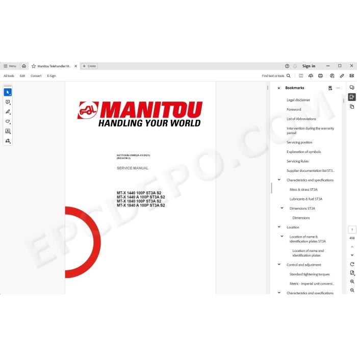
Manitou Telescopic Handler MT-X 1440, MT-X 1440 A, MT-X 1840, MT-X 1840 A 100P ST3A Series 2 pdf service repair manual
Covered models:
MT-X 1440 100P ST3A S2
MT-X 1440 A 100P ST3A S2
MT-X 1840 100P ST3A S2
MT-X 1840 A 100P ST3A S2
MANUAL CONTENT:
GENERAL AND SAFETY CHARACTERISTICS
ENGINE
TRANSMISSION
AXLE
BRAKE
LIFT STRUCTURE
HYDRAULICS
ELECTRICITY
OPERATOR STATION
CHASSIS
ADDITIONAL EQUIPMENT
DIAGNOSTIC TOOLS AND SOFTWARE
GENERAL AND SAFETY CHARACTERISTICS
LIST OF ABBREVIATIONS
WORK DURING THE WARRANTY PERIOD
MAINTENANCE POSITION
EXPLANATION OF SYMBOLS
MAINTENANCE RULES
LIST OF SUPPLIER DOCUMENTATION
CHARACTERISTICS AND SPECIFICATIONS
Weights and forces
Lubricants and fuels
Dimensions
LOCATION
Location of name and identification plates
CONTROL AND ADJUSTMENT
Standard tightening torques
Metric imperial unit conversion
ENGINE
CHARACTERISTICS AND SPECIFICATIONS
Supplier Documentation
LOCATION
Engine components
Diesel fuel circuit
Water + air cooling circuit
CONTROL AND ADJUSTMENT
Fan check points
Accelerator pedal and position sensor adjustment
Adjusting the accelerator solenoid
Engine suspension tightening torques
Engine/gearbox tightening torques
REFIT
Refitting exhaust muffler
TROUBLESHOOTING
Engine assembly error codes
Ignition switching test
Engine start-up authorization conditions
Lack of engine power
Fault table
SPECIFIC TOOLING
Electronic belt tensiometer
TRANSMISSION
CHARACTERISTICS AND SPECIFICATIONS
Supplier Documentation
DIAGRAMS AND SCHEMATICS
Mechanical transmission
LOCATION
Mechanical transmission
CONTROL AND ADJUSTMENT
Mechanical transmission
REMOVAL
Mechanical transmission
TROUBLESHOOTING
General authorization conditions for carriage movement
Transmission DTC error codes
SPECIFIC TOOLING
Basic manometer box
Digital manometer box
Machined 50 mm socket
AXLE
CHARACTERISTICS AND SPECIFICATIONS
Supplier Documentation
CONTROL AND ADJUSTMENT
Bleeding the axle locking cylinder
Adjusting the axle stops when installing wider tires
BRAKE
CHARACTERISTICS AND SPECIFICATIONS
Specifications of the master cylinder
Service brake specifications
Parking brake specifications
DIAGRAMS AND SCHEMATICS
Mechanical transmission
LOCATION
Location of service brake components
CONTROL AND ADJUSTMENT
Mechanical transmission
REMOVAL
Preparation and safety instructions before removal operations on the braking system
Removing the parking brake
Removing the master cylinder
SPECIFIC TOOLING
Hydraulic brake bleed valve
Parking brake bleeder harness
LIFT STRUCTURE
CHARACTERISTICS AND SPECIFICATIONS
Triplex boom MT 14
Quadruplex boom MT 18
DIAGRAMS AND SCHEMATICS
Triplex 14 m boom kinematics
Quadruplex 18 m boom kinematics
LOCATION
Location of components of 14 m triplex boom
Location of 18 m quadruplex boom components
CONTROL AND ADJUSTMENT
Triplex boom
Quadruplex boom
REMOVAL
Triplex boom
Quadruplex boom
REFIT
Triplex boom
Quadruplex boom
SPECIFIC TOOLING
Pipe end pieces
Channel lever
Hose routing support
Hose tension adjustment gage
Chain checking gage
HYDRAULICS
CHARACTERISTICS AND SPECIFICATIONS
List of hydraulic sheets
FP HP feed block + accumulator
component distributor
component electro-proportional distributor PVG100/32
component deflector distributor
Power-assisted brake master cylinder
Hydraulic pump KP30.43
Backup pump EP-45
Steering pump
3-position steering selector
Double safety valve
Single pilot safety valve
Discharge valve VMS
Discharge block valve
Compensating isolation valve
Operation of the compensating isolation valve
Flow rate control valve
Dynamic selection valve
DIAGRAMS AND SCHEMATICS
Hydraulic diagram – MT-X 1440
Hydraulic diagram – MT-X 1840
Hydraulic diagram – MT(-X) A 1440
Hydraulic diagram – MT(-X) A 1840
LOCATION
Location of hydraulic components – MT-X 1440 100P ST3A
Location of hydraulic components – MT-X 1440 A 100P ST3A
Location of hydraulic components – MT-X 1840 100P ST3A
Location of hydraulic components – MT-X 1840 A 100P ST3A
Location of central greasing system lubricators
CONTROL AND ADJUSTMENT
ELECTRICITY
CHARACTERISTICS AND SPECIFICATIONS
Fuses and relays
ECU Inputs/Outputs
Technical sheets for electrical components
DIAGRAMS AND SCHEMATICS
CAN and LIN operating diagram - mechanical transmission
Examples of coding on the wiring diagrams
Cable marking on an electrical wiring harness
Position by diagram - MT-X 100P
Electrical diagrams - MT-X 100P
Position by diagram - MT-X A 100P
Electrical diagrams - MT-X A 100P
LOCATION
Location of electrical components – MT-X 100P
Location of electrical components – MT-X A 100P
CONTROL AND ADJUSTMENT
Checking aggravating hydraulic movement cut-off
Adjust the longitudinal stability limiter and warning device
Adjust the boom angular sensor
REMOVAL
Remove cab fuse and relay access panel
Remove engine fuse and relay access cover
Removing the cab ECU
Removing the instrument panel
Removing the strain gage
Removing the BMEP JSM
REFIT
Refitting the strain gage
Refit the JSM on BMEP
TROUBLESHOOTING
DTC Main ECU (SPU 40-26)
DTC auxiliary ECU (SPU 25-15-STD2) or (SPU 40-26 PWM)
DTC Perkins engine ECU (SPU 25-15)
Automatic air conditioning error codes
SPECIFIC TOOLING
Electrovalve adapter
Breakout boxes
OPERATOR STATION
CHARACTERISTICS AND SPECIFICATIONS
Description of air conditioning operation
Safety measures for handling R134a
DIAGRAMS AND SCHEMATICS
Schematic diagrams
LOCATION
HVAC components
Automatic air conditioning location
Condenser component
CONTROL AND ADJUSTMENT
General checkpoints
Air conditioning assembly instructions
Safety measures for handling R134a
Check the evaporator temperature sensor
Cab air conditioning tightening torques
Cab suspension silent block tightening torques
REMOVAL
Removing the lower dashboard trim panel
Removing the front cab casing
Removing the rear cab casing
Removing the air conditioning heating unit
Removing the cab
Removing the condenser
Removing the motor and electric window
REFIT
Refitting the motor and electric window
TROUBLESHOOTING
Automatic air conditioning error codes
Temperature fault
Unusual noise
Unpleasant smell
CHASSIS
CONTROL AND ADJUSTMENT
Counterweight tightening torque
REMOVAL
Remove the engine hood
ADDITIONAL EQUIPMENT
DIAGNOSTIC TOOLS AND SOFTWARE
DIAGNOSTICS CASE KIT
USB LINK 2 BOX
COMPONENT DIAGNOSTICS BOX
There are no reviews for this product.