Cart
Your shopping cart is empty!
It's never too late to make things right :)


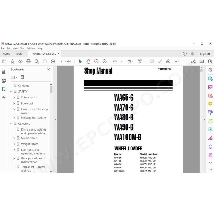
Komatsu Wheel Loader WA65-6, WA70-6, WA80-6, WA90-6, WA100M-6 pdf workshop service manual + operation & maintenance manual
Serial number H60051 and up
Specifications, testing, adjusting, troubleshooting, technical documentation, electrical wiring diagrams, hydraulic schematics, assembly, disassembly, removal, installation instructions and other information
MANUAL CONTENT:
GENERAL
Dimensions, weights and operating data
Specifications
WA65-6 - Specifications
WA70-6 - Specifications
WA80-6 - Specifications
WA90-6 - Specifications
WA100M-6 - Specifications
Weight tables
WA65-6 - Weight table
WA70-6 - Weight table
WA80-6 - Weight table
WA90-6 - Weight table
WA100M-6 - Weight table
Lubricants and operating mediums
WA65-6, WA70-6 - Lubricants and operating mediums
WA80-6 - Lubricants and operating mediums
WA90-6 - Lubricants and operating mediums
WA100M-6 - Lubricants and operating mediums
Basic procedures of maintenance
Oil
Fuel
Coolant
Grease
Storing oil and fuel
Filters
Biodegradable hydraulic oils and lubricants
Outline of electric system
Torque list - Screws and nuts
STRUCTURE AND FUNCTION Powertrain
Closed circuit
Hydraulic drive system
WA65-6, WA70-6 - Hydraulic drive system - 20 km/h
WA80-6 - Hydraulic drive system - 20 km/h and 30 km/h
WA90-6, WA100M-6 - Hydraulic drive system - 20 km/h and 30 km/h
Variable displacement pump (HST pump)
Regulating valve (DA valve)
WA65-6, WA70-6, WA80-6 - Charge pump pressure relief valve - 20km/h
WA80-6 ,WA90-6, 100M-6 - Charge pump pressure relief valve - 30km/h
Control cylinder
4/3 Way valve with direction control solenoids
Pressure cut-off valve
Safety & charge valve
Towing
Variable displacement motor (HST motor with HA Control)
Hydraulic diagram HST motor A6VM80 (or 160) HA1R1
Directional shuttle valve
Auto inch valve diagram (option)
HST motor with DA Control
Hydraulic diagram HST Motor A6VM107(160)DA2
Drive shaft
Front axle - Mounting
WA65-6, WA70-6 - Front axle mounting
WA80-6, WA90-6, WA100M-6 - Front axle mounting
Rear axle - Mounting
Front axle
WA65-6, WA70-6 - Front axle with outer disc brake as service brake and parking brake
WA80-6 - Front axle with inner disc brake as service brake and outer disc brake as parking brake
WA90-6, WA100M-6 - Front axle with inner disc brake as service brake and outer disc brake as parking brake
Rear axle with transfer box
WA65-6, WA70-6, WA80-6 - Rear axle with transfer box
WA90-6, WA100M-6 - Rear axle with transfer box
Trasfer box TB172
Limited slip differential
Limited slip differential - Locking value 25%
Locking differential
Locking differential - Locking value 100%
Wheel hub - Font axle and rear axle
Service and parking brake - Front axle
WA65-6, WA70-6 - Service and parking brake
WA80-6, WA90-6, WA100M-6 - Service brake
WA80-6, WA90-6, WA100M-6 - Parking brake
Service and parking brake circuit
WA65-6, WA70-6 - Service and parking brake circuit
WA80-6 – Service and parking brake circuit
WA90-6, WA100M-6 - Service and parking brake circuit
Service brake assembly
WA65-6, WA70-6 - Service brake assembly
WA80-6 – Service brake assembly
WA90-6, WA100M-6 - Service brake assembly
Main-brake valve
WA65-6, WA70-6 - Main-brake valve
WA80, WA90-6, WA100M-6 - Main-brake valve
Steering articulation joint
Steering system
WA65-6, WA70-6 - Hydraulic circuit diagram of steering system
WA80-6 – Hydraulic circuit diagram of steering system
WA90-6, WA100M-6 - Hydraulic circuit diagram of steering system
Priority valve
Orbit-roll-valve
Steering relief valve
Work equipment hydraulic
WA65-6, WA70-6 - Travel, steering and work hydraulics
WA80-6 - Travel, steering and work hydraulics
WA90-6, WA100M-6 - Travel, steering and work hydraulics
PPC-Valve WA90-6, WA100M-6
Operation of PPC-valve
Servo pressure regulating valve
Emergency Lowering System
Main control valve
Main control valve WA65-6, WA70-6, WA80-6
Main control valve WA90-6, WA100M-6
Lift cylinder
WA65-6, WA70-6 - Lift cylinder
WA80-6 - Lift cylinder
WA90-6 - Lift cylinder
WA100M-6 - Lift cylinder
Dump cylinder
WA65-6, WA70-6 - Dump cylinder
WA80-6 - Dump cylinder
WA90-6 - Dump cylinder
WA100M-6 - Dump cylinder
Steering cylinder
WA65-6, WA70-6 - Steering cylinder
WA80-6 - Steering cylinder
WA90-6, WA100M-6 - Steering cylinder
Loader Linkage with quick-coupler
WA65-6, WA70-6 - Loader Linkage with quick-coupler
WA80-6, WA90-6, WA100M-6 - Loader Linkage with quick-coupler
Quick-coupler
WA65-6, WA70-6 - Quick-coupler
WA80-6 - Quick-coupler
WA90-6, WA100M-6 - Quick-coupler
Monitor display
WA65-6, WA70-6, WA80-6 - Monitor display
WA90-6, WA100M-6 - Monitor display
Special monitor functions
Monitor panel adjustment
Adjustment switches
Adjustment table
WA65-6, WA70-6 Tire table
WA80-6 Tire table
WA90-6 Tire table
WA100M-6 Tire table
Reading error codes WA90-6, WA100M-6
Trouble Codes and Cummins Fault Codes
Sensors
Engine oil pressure sensor
Fuel level sensor
Engine coolant temperature sensor
Brake oil reservoir sensor
Pre-heater
WA65-6, WA70-6, WA80-6 - Glow plugs
WA90-6, WA100M-6 - Ribbon heater
Engine stop / start / preheating circuit
WA65-6, WA70-6, WA80-6
WA90-6, WA100M-6
Electrical fuses and relays
Fuses
Relays
Engine room
Diagrams
Wiring diagrams
Hydraulic circuit diagram
Air conditioner (option)
Introduction
Function
The coolant circuit
The condenser
The vaporizer
The filter dryer
Installation of air conditioner
Safety when handling coolants
Operating the air conditioner
Maintenance of the air conditioner
Regular maintenance
Instructions for filling
Exchange of magnetic clutch
Exchange of compressor
Troubleshooting
TESTING AND ADJUSTING
Standard value table for engine
WA65-6, WA70-6, WA80-6 - Standard value table for engine
WA90-6, WA100M-6 - Standard value table for engine
Standard value table for chassis
WA65-6 - Standard value table for chassis
WA70-6 - Standard value table for chassis
WA80-6 - Standard value table for chassis
WA90-6 - Standard value table for chassis
WA100M-6 - Standard value table for chassis
Standard value table for electrical parts
Test certificate
Valve lash clearance
Engine compression test
Fuel system
WA65-5, WA70-6, WA80-6 - Testing and adjusting fuel injection timing
Testing fuel pressure
Bleeding air from fuel circuit Testing fuel system for leakage
V-belt tension
Engine RPM
Testing travel speed
Engine stall torque RPM
Engine stall torque RPM, test with the hydrostatic drive
Engine stall torque RPM, test with hydrostatic drive and working hydraulics
Feed pump (and servo oil pressure)
Hydraulic pressure cut-off
Working hydraulic pressure
Steering oil pressure
Testing
Adjusting
Operating time for steering wheel
Operating force of steering wheel
Disc brake (foot brake)
Brake
Main brake valve – basic adjustment
Brake efficiency
Measuring the stopping distance
Parking brake efficiency
Bleeding/ filling up the brake circuit
WA65-6, WA70-6 - Bleeding/ filling up the brake circuit
Ventilation / filling up the brake circuit
WA80-6, WA90-6, WA100M-6 - Ventilation / filling up the brake circuit
Cabin - adjustment
Proportional amplifier
DISASSEMBLY AND ASSEMBLY
Starter assembly
Removal of starter assembly
Installation of starter assembly
Alternator assembly
Removal of alternator assembly
Installation of alternator assembly
Radiator assembly
Removal of radiator assembly
Installation of radiator assembly
Fan assembly
Removal of fan assembly
Installation of fan assembly
Water pump assembly
Removal of water pump assembly
Installation of water pump assembly
Fuel tank assembly
Removal and installation of fuel tank assembly
Installation
Engine cover assembly
Removal of engine cover assembly
Installation of engine cover assembly
Engine cover support assembly
Removal of engine cover support assembly
Installation of engine cover support assembly
Engine assembly
Removal of engine assembly
Installation of engine assembly
Clutch assembly
Removal of clutch assembly
Installation of clutch assembly
Main brake valve assembly
Removal of main brake valve assembly
Installation of main brake valve assembly
Priority valve assembly
Removal of priority valve assembly
Installation of priority valve assembly
Orbit-roll-valve assembly
Removal of orbit-roll-valve assembly
Installation of orbit-roll-valve assembly
Counterweight assembly
Removal of counterweight assembly
Installation of counterweight assembly
Main control valve assembly - WA65-6, WA70-6, WA80-6
Removal of control valve assembly
Installation of main control valve assembly
Main control valve assembly - WA90-6, WA100M-6
Removal of main control valve assembly
Installation of main control valve assembly
Pilot valve assambly WA90-6, WA100M-6
Removal of pilot valve assembly
Installation of pilot valve assembly
Monitor assembly
Removal of monitor assembly
Installation of monitor assembly
Articulated joint assembly
Removal of articulated joint assembly
Installation of articulated joint assembly
Variable motor assembly
Removal of variable motor assembly
Installation of variable motor assembly
Rear axle assembly
Removal of rear axle assembly
Installation of rear axle assembly
Front axle assembly
Removal of front axle assembly
Installation of front axle assembly
Front axle
Brake disc group
Brake caliper
Hydraulic principle of operation
Differential position
Mechanical principle of operation
Caliper removal
Disassembly (calliper removed)
Caliper reassembly
Replacement of guide protective covers
Pad replacement
Brake group - wheel shaft
Rear axle
Trunnions group and flange
Epicyclic reduction gear group
Wheel hub
Wheel shaft - WA65-6, WA70-6
Wheel shaft - WA80-6, WA90-6, WA100M-6
Differential support group
Bevel gear marking test
Differential locking group
Differential group (100% Differential Lock)
Differential group (LSD 25%)
Pinion group
Transmission box
Variable displacement pump assembly
Removal of variable displacement pump assembly
Installation of variable displacement pump assembly
Hydraulic pump assemblies
Removal of the two hydraulic pump assemblies
Installation of hydraulic pump assembly
Turbocharger assembly
Removal of the turbocharger
Installation of the turbocharger
Quick coupler assembly
Removal of quick coupler assembly
Installation of quick coupler assembly
Steering cylinder assembly
Removal of steering cylinder assembly
Installation of steering cylinder assembly
Lift cylinder assembly
Removal of lift cylinder assembly
Installation of lift cylinder assembly
Dump cylinder assembly
Removal of dump cylinder assembly
Installation of dump cylinder assembly
Replacing windows in drivers cab
Stuck glass
Door and side windows
Door window assembly
Side window assembly
OTHERS
Hydraulic circuit diagram
Wiring diagram
Engine 4D95LWE-5, S4D95LWE-5, SAA4D95LE-5 series workshop service manual
There are no reviews for this product.