Cart
Your shopping cart is empty!
It's never too late to make things right :)


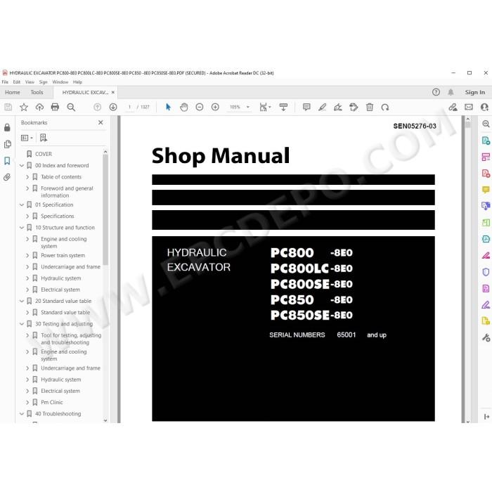
Komatsu Hydraulic Excavator PC800-8E0, PC800LC-8E0, PC800SE-8E0, PC850-8E0, PC850SE-8E0 pdf workshop service manual + operation & maintenance manual
Serial numbers:
PC800-8E0 65001 and up, K55001 and up
PC800LC-8E0 65001 and up, K55001 and up
PC800SE-8E0 65001 and up, K55001 and up
PC850-8E0 65001 and up, K55001 and up
PC850SE-8E0 65001 and up, K55001 and up
Specifications, testing, adjusting, troubleshooting, technical documentation, electrical wiring diagrams, hydraulic schematics, assembly, disassembly, removal, installation instructions and other information
MANUAL CONTENT:
Specification
Specifications drawing
Table of weight
Table of fuel, coolant and lubricants
Structure and function
Engine and cooling system
Coupling
Coupling lubrication system
Cooling system
Power train system
Power train
Swing circle
Swing machinery
Final drive
Undercarriage and frame
Track frame
Idler cushion
Hydraulic system
Hydraulic component layout
Hydraulic tank and filter
Hydraulic pump
Pump control system
Servo valve
Self-pressure reducing valve
Cooling fan pump
Cooling fan motor
Electrical grease pump
Control valve
Straight-travel valve
Swing motor
PPC valve
Solenoid valve
Accumulator
Quick return valve
Return oil filter
Line oil filter
Pilot oil filter
Drain oil filter
Electrical system
Engine control
Electric control system
Monitor system
Sensors
KOMTRAX system
Standard value table
Standard value table for engine
Standard value table for machine
Testing and adjusting
Tools for testing, adjusting, and troubleshooting
Engine and cooling system
Testing engine speed
Testing intake air pressure (boost pressure)
Testing exhaust gas temperature
Testing exhaust gas color
Adjusting valve clearance
Testing compression pressure
Testing blowby pressure
Testing engine oil pressure
Testing EGR valve and bypass valve drive pressure
Handling fuel system parts
Releasing remaining pressure from fuel system
Testing fuel pressure
Testing fuel return rate and leakage
Bleeding air from fuel circuit
Testing fuel circuit for leakage
Testing and adjusting alternator belt tension
Testing and adjusting air conditioner compressor belt tension
Undercarriage and frame
Testing swing circle bearing clearance
Checking and adjusting track tension
Hydraulic system
Testing and adjusting oil pressure in work equipment, swing, and travel circuits
Testing and adjusting control circuit oil pressure (output pressure of self-pressure reducing valve)
Troubleshooting
General information on troubleshooting
Points to remember when troubleshooting
Sequence of events in troubleshooting
Checks before troubleshooting
Classification and procedures for troubleshooting
Failure codes table
Symptom and troubleshooting numbers
Information in troubleshooting table
Troubleshooting method for open circuit in wiring harness of pressure sensor system
Connector list and layout
Connection table for connector pin numbers
T- branch box and T- branch adapter table
Fuse locations
Troubleshooting by failure code
Disassembly and assembly
General information on disassembly and assembly
How to read Disassembly and Assembly
Coating materials list
Special tools list
Sketches of special tools
Engine and cooling system
Power train
Undercarriage and frame
Hydraulic system
Work equipment
Cab and its attachments
Electrical system
Maintenance standard
Engine and cooling system
Coupling
Power train
Swing circle
Swing machinery
Final drive
Sprocket
Undercarriage and frame
Track frame and idler cushion
Idler
Carrier roller
Track roller
Track shoe
Hydraulic system
Cooling fan motor
Control valve
Swing motor
Center swivel joint
PPC valve
Work equipment
Work equipment dimension
Hydraulic cylinder
Air conditioner
Precautions for refrigerant
Air conditioner component
Configuration and function of refrigeration cycle
Outline of refrigeration cycle
Air conditioner unit
Air conditioner controller
Compressor
Condenser
Receiver drier
Procedure for testing and troubleshooting
Circuit diagram and arrangement of connector pins
System diagram
Detail of air conditioner unit
Parts and connectors layout
Testing air leakage (duct)
Testing with self-diagnosis function
Testing temperature control
Testing vent (mode) changeover
Testing FRESH/RECIRC air changeover
Testing inner sensor
Testing evaporator temperature sensor
Testing sunlight sensor
Testing (dual) pressure switch for refrigerant
Testing relay
Diagrams and drawings
Symbols used in hydraulic circuit diagrams
Hydraulic circuit diagram
Symbols used in electric circuit diagrams
Electrical circuit diagram
Engine SAA6D140E-5 workshop service manual
There are no reviews for this product.