Cart
Your shopping cart is empty!
It's never too late to make things right :)


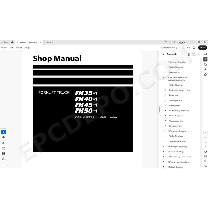
Komatsu Forklift Truck FH35-1, FH40-1, FH45-1, FH50-1 pdf workshop service manual
Serial numbers 138001 and up
Technical documentation, specifications, troubleshooting, maintenance, testing, electrical diagrams, hydraulic schematics, adjusting, assembly, disassembly, removal, installation instructions and other information
MANUAL CONTENT:
Index and foreword
Foreword and general information
Safety notice
How to read the shop manual
Explanation of terms for maintenance standard
Handling of electric equipment and hydraulic component
Handling of connectors newly used for engines
How to read electric wire code
Precautions when carrying out operation
Standard tightening torque table
Conversion table
General Information
Specification dimensions drawing
Weight table
Lubricant list
List of specified fuel and lubricant
Structure, function and maintenance standard
Engine and cooling system
Engine mount and transfer mount
Cooling system
Power train
Power train system diagram
PTO
HST piping diagram
HST pump
HST motor
Axle
Differential
Steering system
Steering piping diagram (control valve – power steering cylinder)
Orbitrol valve
Power steering cylinder
Brake system
Brake control
Brake piping diagram (control valve – accumulator)
Service brake
Accumulator charge valve
Brake valve
Slack adjuster
Accumulator (for brake)
Parking brake
Undercarriage and frame
Rear axle
Hydraulic tank piping diagram
Frame
Hydraulic system
Control valve piping diagram (tank – control valve)
Work equipment piping diagram (control valve – tilt cylinder/lift cylinder)
Attachment piping diagram
Work equipment control lever linkage
Work equipment and steering pump
Control valve
CLSS
Each function and operation of each valve
Work equipment
Tilt cylinder
Lift cylinder
Mast
Finger board
Fork
Electrical system
Electrical control system
HST controller
Engine controller
Accelerator pedal sensor
EPACS controller
Instrument panel
Pilot box
DC/DC converter
KOMTRAX system
Sensor
Combination switch
Seat switch
Service switch/Preheater lamp
Flasher unit
Relay box
Relay
Standard value table
Testing and adjusting
Check of failure code of engine controller
Displaying, setting, checking by using HST controller
Travel speed control function for general operator (description in Operation and Maintenance Manual of the lift truck)
Setting controlled travel speed
Maximum travel speed control function
Banning function of changing controlled travel speed
Electricalsystem abnormality record display function (only for HST controller system)
Mechanicalsystem abnormality record display function
Adjusting function
Memory clear function
Automatic engine stop set interval changing function
Releasing pressure from hydraulic piping
Replacement of engine oil and engine oil filter
Replacement of fuel filter
Fuel prefilter water drain
Fuel filter air bleeding
Radiator cleaning
Air cleaner inspection and element replacement
Testing and adjusting engine speed
Testing and adjusting HST oil pressure
Testing work equipment and steering pump oil pressure
Oil level check and changing oil in differential case
Changing PTO oil and cleaning strainer
Inspection of hydraulic tank
Measuring brake performance
Measurement of wear of service brake disc
Checking parking brake
Bleeding air
Adjusting brake pedal
Testing and adjusting brake pedal angle sensor linkage
Initial setting of Orbitrol valve
Measurement of hydraulic drift and forward tilt down by hydraulic drift of cylinder
Adjustment of mast
Adjustment of fork carriage
Lamp display of KOMTRAX terminal
KOMTRAX terminal startup procedure
Troubleshooting
Information related to troubleshooting
Points to remember when troubleshooting
How to proceed in troubleshooting
Checks before troubleshooting
Classification and procedures of troubleshooting
Phenomena seemed to be failures and troubleshooting Nos
Information described in troubleshooting table
Locations of fuses
Connection table for connector pin numbers
T-branch box and T-branch adapter table
Troubleshooting by failure code (HST controller system)
Troubleshooting by failure code (EPACS controller system)
Troubleshooting for electrical system (E-mode)
Troubleshooting for hydraulic and mechanical system (H-mode)
Disassembly and assembly
Related information on disassembly and assembly
How to read this manual
Coating materials list
Special tools list
Sketches of special tools
How to use Loctite
Engine and cooling system
Removal and installation of fuel supply pump assembly
Removal and installation of fuel injector assembly
Removal and installation of cylinder head assembly
Removal and installation of of radiator assembly
Removal and installation of aftercooler assembly
Removal and installation of oil cooler assembly
Removal and installation of engine and pump assembly
Removal and installation of starting motor assembly
Power train
Removal and installation of front axle and HST motor assembly
Disassembly and assembly of front axle assembly
Removal and installation of PTO assembly
Disassembly and assembly of PTO assembly
Disassembly and assembly of differential assembly
Disassembly and assembly of axle housing assembly
Disassembly and assembly of parking brake assembly
Disassembly and assembly of rear axle assembly
Disassembly and assembly of power steering cylinder assembly
Disassembly and assembly of brake pedal assembly
Undercarriage and frame
Removal and installation of counterweight assembly
Removal and installation of head guard assembly
Removal and installation of hood assembly
Hydraulic system
Removal and installation of HST pump assembly
Removal and installation of HST motor assembly
Removal and installation of work equipment and steering pump assembly
Removal and installation of control valve assembly
Disassembly and assembly of control valve assembly
Disassembly and assembly of orbitrol valve assembly
Removal and installation of lift cylinder assembly
Disasse mbly and assembly of lift cylinder assembly
Disassembly and assembly of tilt cylinder assembly
Work equipment
Removal and installation of mast assembly
Disassembly and assembly of mast assembly
Electrical system
Removal and installation of engine controller assembly
Removal and installation of HST controller assembly
Removal and installation of KOMTRAX terminal assembly
Disassembly and assembly of combination switch assembly
Yearly inspection criteria
Circuit diagrams
Hydraulic circuit diagram
Electrical circuit diagram
There are no reviews for this product.