Cart
Your shopping cart is empty!
It's never too late to make things right :)


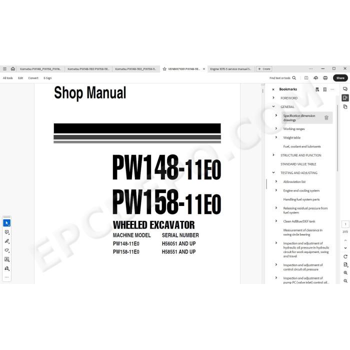
Komatsu Wheeled Excavator PW148-11E0, PW158-11E0 pdf workshop service & repair manual
Serial numbers:
PW148-11E0 H56051 and up
PW158-11E0 H58551 amd up
Technical documentation, specifications, troubleshooting, maintenance, electrical diagrams, hydraulic schematics, adjusting, assembly, disassembly, removal, installation instructions and other information
MANUAL CONTENT:
GENERAL
Specification dimension drawings
Dimensions PW148-11E0
Dimensions PW158-11E0
Working ranges
Working range: 1-piece boom
Working range: 2-piece boom
Weight table
1-piece boom
2-piece boom
Fuel, coolant and lubricants
STRUCTURE AND FUNCTION
UREA SCR system
Layout drawing of UREA SCR system
UREA SCR system diagram
Component parts of UREA SCR system
SCR assembly
AdBlue/DEF tank
BOOT-UP system
Layout drawing of BOOT-UP system
System operating lamp system
Battery disconnect switch
Engine system
Layout drawing of engine system
Engine control system
Auto-deceleration system
Engine automatic warm-up system
Overheat prevention system
Turbocharger protection system
Automatic idle stop system
Component parts of engine system
Crankcase ventilation system
Exhaust throttle valve
KDPF
Cooling system
Engine output control system of fan clutch
Component parts of cooling system
Power train
Swing circle
Swing machinery & motor
Operation of swing lock
Relief valve portion
Undercarriage
Transmission
Trailer
Calculation of maximum coupling Load
Automatic trailer coupling for blade
Automatic Trailer Coupling For Outrigger
Inspection
2nd Auxiliary circuit in the undercarriage
Hydraulic quick coupler
Full hydraulic quick coupler
Travel motor
Operation of travel motor
Clutch control circuit
Axle
Suspension lock cylinder
Braking system
Gear pump
Priority valve
Power brake valve
Accumulator for brake valve
Digging brake valve
Steering system
Joystick steering system
Structure and function
Steering column JSS
Specifications
Steering column STD
Steering column JSS
Orbitrol valve STD
Orbitrol valve JSS
Hydraulic equipment layout drawings
Hydraulic circuit diagram
Hydraulic tank
Hydraulic pump
LS valve
PC valve
LS(PC)-EPC valve
Pilot pressure control (PPC) system
Control main valve
CLSS
Outline of CLSS
Basic Principle
Operation for each function and valve
1.Unload valve
2.Introduction of LS pressure
3.LS bypass plug
4.Pressure compensation valve
5.Area ratio of pressure compensation valve
6.Boom regeneration circuit
7.Arm regeneration circuit
8.Swing bleeding valve
9.LS select valve
Centre swivel joint
Travel PPC pedal
Work equipment – Swing PPC valve
Solenoid valve block with integrated ATT - EPC
ON / OFF Solenoid valves (3 way valve)
Attachment PPC valve
Undercarriage solenoid valve block
Boom/Outrigger schematic
Undercarriage attachment schematic
Proportional attachment control
Proportional attachment schematic
Bucket to 1ATT
Function
Boom safety valve
Boom floating
Hydraulic cylinder
Boom cylinder
Arm cylinder
Bucket cylinder
Adjust cylinder
Outrigger cylinder
Dozer cylinder
Work equipment
1.Dimension of arm
2.Dimension of bucket
Tool control
ECSS
Breaker return valve
Air conditioner
Air conditioner component
Specifications of air conditioner
Electrical wiring diagram
Electrical system
Engine control
Engine controller
Structure of engine controller
Pump controller
Machine controller
Machine control system diagram
Machine monitor system
Function of machine monitor
Monitor display
Monitor items and display
Caution monitor
Pilot monitor
Monitor switches
KOMTRAX system
Gateway Controller
KomVision system
Layout drawing of KomVision system
KomVision controller
Structure of KomVision controller
Structure of KomVision camera
Overload warning device
Outline
Sensors
Ambient pressure sensor
Charge (boost) pressure and temperature sensor
Coolant temperature sensor
Ne (crankshaft) speed sensor
Bkup (camshaft) speed sensor
Common rail pressure sensor
Exhaust manifold pressure sensor
Mass air flow and temperature sensor
KDOC inlet temperature sensor
KDOC outlet temperature sensor
Engine oil level sensor
Fuel level sensor
WIF (Water-In-Fuel detection) sensor
Coolant level sensor
Air cleaner clogging sensor
Overload Caution sensor
Swing proximity sensor
Brake sensors
Main valve sensor
PPC levers
1st attachment circuit hydraulic performance (main valve bypassed)
Travel system
Travel circuit
Auto-grease pump
Lubrication diagrams
STANDARD VALUE TABLE
Standard value table for engine related parts
Standard value table for chassis related parts
PM clinic service
TESTING AND ADJUSTING
Engine and cooling system
Test engine speed
Test boost pressure
Test exhaust gas colour
Test and adjust valve clearance
Test compression pressure
Test blow by pressure
Test engine oil pressure
Handling fuel system parts
Releasing residual pressure from fuel system
Test fuel pressure
Method for testing fuel pressure
Test fuel discharge, return and leakage
Method for testing fuel discharge, return and leakage
Bleeding air from fuel system
Test fuel circuit for leakage
Test and adjust air conditioner compressor belt tension
Replacing the fan belt
Test cooling fan speed
Write ash in soot accumulation correction to engine controller
Test SCR related functions
Test AdBlue/DEF pump raised pressure
Method for testing AdBlue/DEF pump raised pressure
Test injection amount from AdBlue/DEF injector
Method for testing injection amount from AdBlue/DEF injector
Test AdBlue/DEF line heater relay
Test AdBlue/DEF pump heater relay
Test AdBlue/DEF tank heater valve
Test denitration efficiency of SCR
Clean AdBlue/DEF tank
Bleed air from coolant circuit of AdBlue/DEF tank
Measurement of clearance in swing circle bearing
Inspection and adjustment of hydraulic oil pressure in hydraulic circuit for work equipment, swing and trave
Inspection and adjustment of control circuit oil pressure
Inspection and adjustment of pump PC (valve inlet) control oil pressure
Inspection and adjustment of pump LS differential pressure
Measurement of solenoid valve output pressure
Adjustment of work equipment and swing PPC valve
Measuring and adjusting quick coupler control valve output pressure
Testing travel motor relief pressure
Testing propshaft speed
Testing transmission clutch control circuit
Inspection of locations of hydraulic drift of work equipment
Release of remaining pressure in hydraulic circuit
Measurement of oil leakage
Air bleeding of various parts
Inspection procedures for diode
Electrical system
Set and operate machine monitor
Method for starting up KOMTRAX terminal
Inspection and adjustment of ECSS (ACCU pressure)
Inspection and adjustment of Tool control
Troubleshooting
Changing the lubrication interval times
Changing the Joystick steering control
Inspection and adjustment digging brake system
Adjust rearview camera angle
Method for adjusting rear view camera angle
Adjust KomVision camera angle
Method for adjusting KomVision camera angle
Angle adjustment method for front R.H camera, rear R.H camera, and rear L.H camera
Angle adjustment method for rear camera
Adjust KomVision related items
Setting of KomVision (main setting)
Setting of KomVision (camera setting)
Setting of KomVision (camera calibration)
TROUBLESHOOTING
Related information on troubleshooting
General troubleshooting points
Sequence of events in troubleshooting
Connector table
T-Branch box and T-Branch adapter table
Fuse location table
Failure code table (Display of code)
Troubleshooting by failure code (Display of code)
MAINTENANCE STANDARD
Engine and cooling system
Maintenance standard of engine mount
Maintenance standard of cooling system
Power train
Maintenance standard of swing circle
Maintenance standard of swing machinery
Axles
Gear box
Prop shaft
Orbitrol valve (STD/JSS)
Trailer preparation
Cabin mounting
Hydraulic system
Maintenance standard of hydraulic tank
Main pump
Maintenance standard of LS-EPC valve
Maintenance standard of PC-EPC valve
Control valve
Maintenance standard of anti-drop valve for 1boom LH
Maintenance standard of anti-drop valve for 1boom RH
Maintenance standard of anti-drop valve for 2boom
Maintenance standard of anti-drop valve for arm/bucket
Maintenance standard of work equipment and swing PPC valve
Solenoid valve block
Swivel joint
Work equipment
Work equipment linkage
1Dimension of arm
2Dimension of bucket
Hydraulic cylinder
Boom cylinder
Arm cylinder
Bucket cylinder
Adjust cylinder
APPENDIX
Air conditioner system
Precautions for refrigerant
Air conditioner component
Specifications of air conditioner
Outline of refrigeration cycle
Component parts of air conditioner system
Air conditioner unit
Configuration diagram of air conditioner unit
Component parts of air conditioner unit
Air conditioner controller
Compressor
Condenser
Sensors for air conditioner system
Function of sunlight sensor
Explanation of procedure for testing and troubleshooting of air conditioner
Circuit diagram and arrangement of connector pins for air conditioner
Air conditioner system diagram
Input and output signals of air conditioner controller
Installation locations of air conditioner parts and arrangement of connectors
Testing air leakage (DUCT)
Method for testing air leakage (DUCT)
Testing air conditioner using self-diagnosis function
How to open the electrical system abnormality record screen in service mode of the machine monitor
Test vent (mode) changeover
Testing FRESH/RECIRC air changeover
Method for testing FRESH/RECIRC air changeover
Test sunlight sensor
Method for testing sunlight sensor
Test (dual) pressure switch for refrigerant
Method for testing (dual) pressure switch for refrigerant
Test relays
Method for testing relays
Air conditioner troubleshooting chart
Information described in troubleshooting table
Failure code [879AKA] A/C recirculation air temperature sensor open circuit
Failure code [879AKB] A/C recirculation air temperature sensor short circuit
Failure code [879BKA] A/C fresh air temperature sensor open circuit
Failure code [879BKB] A/C fresh air temperature sensor short circuit
Failure code [879CKA] Ventilating sensor open circuit
Failure code [879CKB] Ventilating sensor short circuit
Failure code [879DKZ] Sunlight sensor open circuit or short circuit
Failure code [879EMC] Ventilation damper malfunction
Failure code [879FMC] Air mix damper malfunction
Failure code [879GKX] Refrigerant pressure input signal out of range
A-1 Troubleshooting for power supply system (air conditioner does not operate)
A-2 Troubleshooting for compressor and refrigerant system (air is not cooled)
A-3 Troubleshooting for blower motor system (no air comes out or air flow is abnormal)
A-4 Troubleshooting for FRESH/RECIRC air changeover
Troubleshooting using gauge pressure
Connection of service tool
Method for connecting service tool
Precautions for disconnection
Handle compressor oil
Method for replacing desiccant
Joystick Steering
Overview of failure groups and descriptions
Error handling
Malfunction of Pump controller
Joystick activation signals have the same value
Malfunction of SASA-sensor
CRC
CAN Count
CAN Timeout
Sensor chip
Steering angle
CAN Input Message
Power
CPU
Memory
Temperature
Angle Not Available (from CAN)
RPM Not Available (from CAN)
CAN Redundant
Sensor
RAM Corruption
Malfunction of Hall-sensor
Joystick signals out of range
Joystick redundant signals mismatch
Joystick out of neutral when activating steering system
No signal available
Malfunction of PVES (electrical activation) Orbitrol
Steering valve feedback value out of range (beneath 25% UDC or above 75% UDC)
Steering valve feedback (SP) value and control value (US) mismatch
Error pin (C2p01) high signal, also indicated on PVES-SP LED
Wiring-failure
Joystick signals out of range
Joystick redundant signals mismatch
Joystick Mode signals have the same value
Cut Off valve current output and feedback mismatch
Steering valve supply current output and feedback mismatch
Steering valve control duty output and feedback mismatch
Steering valve control
Steering valve supply
Steering valve failure signal
Cut Off valve outputs
Joystick mode switch reference
Failure LED output
Joystick mode inputs
Joystick active inputs
Joystick signals
Steering valve failure signal input
Steering valve position feedback input
Miscellaneous
CAN time out
Joystick calibration failure
SASA Sensor CAN Timeout
CAN bus failure
Bus Off
Driver Error
Passive Mode Error
Overflow
Joystick Mode signals have the same value
Joystick steering profile parameters out of range
Failure of SC024-120
HWPCBVoltages.InRange
OS.CrcStatus
OS.ChecksumFailure
SafetyLayer.Failure
Battery power outside of allowable ranges
Sensor power outside of specified ranges
NVMem.Status
Error descriptions
Inputs
Safety function
Outputs
Joystick controller internal
Error Counters Page
Acronyms
OTHER
Hydraulic circuit diagram
Electrical circuit diagram
Engine SAA4D107E-5 workshop service repair manual
There are no reviews for this product.