Cart
Your shopping cart is empty!
It's never too late to make things right :)


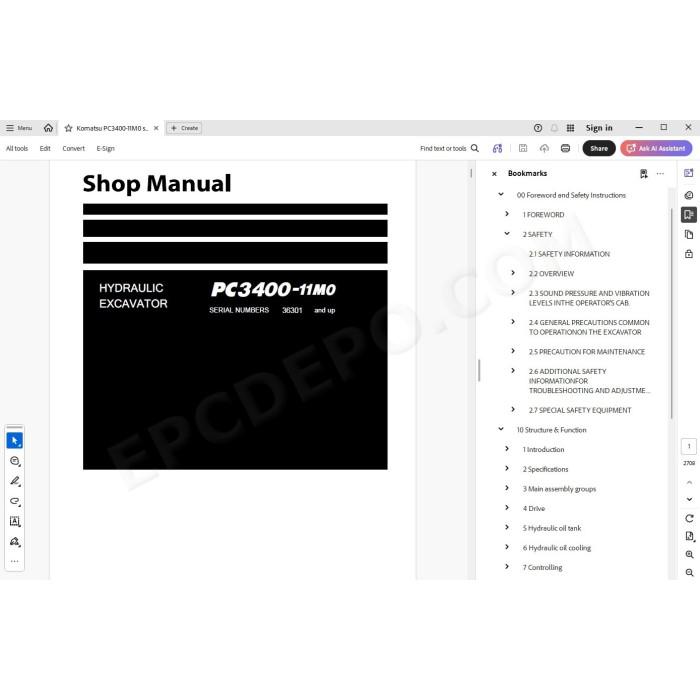
Komatsu Hydraulic Excavator PC3400-11M0 pdf workshop service manual
Serial numbers 36301 and up
Technical data, specifications, testing, adjusting, troubleshooting, maintenance, electrical wiring diagrams, hydraulic schematics, circuits, assembly, disassembly, removal, installation instructions and other information
MANUAL CONTENT:
Foreword and Safety Instructions
1 FOREWORD
1.1 BEFORE READING THIS MANUAL
1.2 CONTENTS OF THIS BINDER
1.3 DIVISION OF THE BINDER
SAFETY
2.1 SAFETY INFORMATION
2.2 OVERVIEW
2.3 SOUND PRESSURE AND VIBRATION LEVELS INTHE OPERATOR’S CAB
2.4 GENERAL PRECAUTIONS COMMON TO OPERATIONON THE EXCAVATOR
2.5 PRECAUTION FOR MAINTENANCE
2.6 ADDITIONAL SAFETY INFORMATIONFOR TROUBLESHOOTING AND ADJUSTMENTS
2.7 SPECIAL SAFETY EQUIPMENT
Structure & Function
1 Introduction
1.1 Foreword
1.2 Recommendations for environmentally friendly operation and maintenance of hydraulic mining excavators
1.3 Explanation of abbreviations
1.4 Diagrams and illustrations in this manual
2 Specifications
2.1 Lifting Gears
2.2 Safety hints for sling accessory
2.3 Standard Tightening Torque Chart
2.4 Special Tightening Torques
2.5 Torque for flange Joints
2.6 Tightening Torque for hydraulic hose connecting nut
2.7 Conversion Table
2.8 Blind plugs
3 Main assembly groups
3.1 General overview
3.2 Superstructure
3.3 Machine house
3.4 Hydraulic oil tank
3.5 Hydraulic oil cooler
3.6 Fuel tank
3.7 Cab base
3.8 Operator’s cab
3.9 Air conditioning
3.10 Main control valves
3.11 Slew Gearbox
3.12 Undercarriage
3.13 Slew ring
3.14 attachment
3.15 Safety circuit
3.16 Counterweight
3.17 Lubrication system (SLS & CLS)
4 Drive
4.1 Prime drive assembly
4.2 Engine and PTO mounts
4.3 Flexible coupling
4.4 Fan drive and radiator assembly
4.5 Pump distributor gearbox (PTO)
4.6 Hydraulic pumps – location, drive speed and flow rates
4.7 Air filter
5 Hydraulic oil tank
5.1 General layout
5.2 Hydraulic oil tank, location of the electric equipment
5.3 Suction oil tank with strainers
5.4 Bypass valve with strainer
5.5 Back pressure valve
5.6 Transfer pump
5.7 Return and leak oil filter
5.8 Breather filter
5.9 Hydraulic oil tank bleeding instruction
5.10 Return oil filter chamber sight gauge
6 Hydraulic oil cooling
6.1 Overall view of the hydraulic oil coolers
6.2 Fan pump
6.3 Overview of the oil cooler circuit
7 Controlling
7.1 General layout PPC line
7.2 Valve cartridge block
7.3 Pilot pressure supply
7.4 Main control valves designation
7.5 Function of the electronic pump & bleed control system
7.6 Foot pedal control
7.7 Hand lever & foot pedal monitoring
7.8 Valve solenoid adjustment
7.9 ACCEL & DECEL time adjustment
8 Components
8.1 Main control valves overview (BHA)
8.2 Main control valves overview (FSA)
8.3 Main control valve designation (BHA)
8.4 Main control valve designation (FSA)
8.5 Main control valves designation
8.6 Main control valve
8.7 Main control valve 3
8.8 Boom operation sample MCV 2 (BHA)
8.9 Spool types
8.10 Main control valves spool functions (BHA)
8.11 Main control valves spool functions (FSA)
8.12 Slow return valve
8.13 4/3 Directional solenoid valves
8.14 Solenoid valves
8.15 Solenoid valve
8.16 EPC solenoid valve
8.17 High-pressure screen
8.18 Main relief valve
8.19 Suction & safety relief valve (SSRV)
8.20 Suction valve (SV)
8.21 Load check valve
8.22 Variable back pressure valve
8.23 Boom regeneration valve
8.24 Hydraulic cylinder
9 Main hydraulic pumps and pump regulation
9.1 General
9.2 Main pumps
9.3 Electronic pump regulation system
9.4 Valve controller (14K303 - 14K305)
9.5 Monitoring, error indication, adjustment
9.6 Checks and adjustments
9.7 Engine speed sensor (pick-up)
10 Operating hydraulics
10.1 General
10.2 Hydraulics for the attachment cyLinders
10.3 Hydraulics for the slew circuit
10.4 Hydraulics for the travel system
10.5 Travel brake valve
11 Hydraulic track tensioning system
11.1 General
11.2 Functional description
11.3 Tensioning cylinder
11.4 Double stage valve
11.5 Checks / Adjustments
12 Access stairway, hydraulically operated
12.1 General
12.2 Function of the hydraulically operated access stairway
12.3 Hydraulic schematic stairway movement
13 Central refilling system (Service arm)
13.1 General
13.2 Service arm connections
13.3 Refilling system layout
13.4 Grease refill and Auto Stop function
13.5 Function
14 Symbol explanation of hydraulic diagram
14.1 Reference code of the hydraulic components
14.2 Hydraulic symbols
14.3 Hydraulic circuit diagram
15 Symbol explanation electric wiring diagram
15.1 Reference code of the electrical components
15.2 Cable and connector marking
15.3 Cable color identification
15.4 ELECTRICAL CIRCUIT DIAGRAM
16 Monitoring & Control System
16.1 General
16.2 Machine monitor - Operator level
16.3 Error and status indication on the operator level
16.4 Table of failure codes
16.5 Table of C-codes - Diesel engine Tier2
16.6 Flow charts of machine monitor screens
16.7 Machine monitor
16.8 Service Menu - item 01 Monitoring / Custom
16.9 Service Menu - item 02 PM Clinic
16.10 Service Menu - item 03 Abnormality record
16.11 Service Menu - item 04 Maintenance record
16.12 Service Menu - item 05 Maintenance Mode Setting
16.13 Service Menu - item 06 Snap Shot
16.14 Service Menu - item 07 Phone Number Entry
16.15 Service Menu - item 08 Default
16.16 Service Menu - item 09 Unit
16.17 Service Menu - item 10 Adjustment
16.18 Service Menu - item 11 Machine Configuration
16.19 Service menu: item 12 Fan reverse mode
16.20 Service menu: Item 13 Cylinder Cushion control calibration
16.21 Service menu: Item 14 Pump calibration
16.22 Automatic engine speed control
16.23 KOMTRAX Plus controller (UM600)
16.24 CR730 controller
16.25 Controller replacement procedure
17 Lubrication system
17.1 Lubrication system (SLS & CLS)
17.2 Basic function of the lubrication systems
17.3 Grease refill and Auto Stop function
17.4 Lubrication System (CLS & SLS)
17.5 Lubrication cycle
17.6 Hydraulically driven lube pump
17.7 Lubricant injectors
17.8 Vent valve
17.9 Lubricant level sensors
17.10 Commissioning
18 Deep temperature equipment (option)
18.1 General information
18.2 Preheating procedure
18.3 Electric heating elements
18.4 Components of TT equipment
Troubleshooting
1 Introduction
Precautions before work
1.1 Overview
1.2 General precautions
2 General information for troubleshooting
2.1 Preparations for work
2.2 Precautions during work
2.3 Precautions when carrying out any operation
2.4 Fundamental requirements for trouble shooting
2.5 Points to remember when troubleshooting
2.6 Sequence of events In troubleshooting
2.7 Checks before troubleshooting
2.8 Handling of electric equipment and hydraulic components
2.9 General working procedures
2.10 Basics about "How to crimp" (with strain relief)
2.11 Cable shielding
3 Mounting locations and connector types
3.1 Location of emergency shut off - , stairway and service arm lowering devices
3.2 Location of battery box and emergency stop switches
3.3 Location of service safety switch
3.4 Location of engine related electrical components
3.5 Location of fuel supply, PTO and hydraulic pumps electrical components
3.6 Location of valve cartridge block electrical components
3.7 Location of main blocks electrical components
3.8 Location of SLS and CLS electrical components
3.9 Location of SLS pressure sensor
3.10 Location of CLS pressure sensor
3.11 Location of fuel tank electrical components
3.12 Location of hydraulic oil cooler electrical components
3.13 Location of cab base electrical components (location 14)
3.14 Location of cab base electrical components (location 11)
3.15 Location of hydraulic oil tank & suction oil tank electrical components
3.16 Location of bypass valve electrical components
3.17 Location of electrical components on hydraulically operated access stairway
3.18 Location of service arm electrical components
3.19 Location of electrical components on cushion function
3.20 Location of electrical components on boom recirculation valve
3.21 Location of electrical components on distributor manifold
3.22 Location of electrical components for slew left/right circuit
3.23 Location of electrical components for travel circuit
3.24 Connector types overview
4 Standard value table for electrical components
5 Tables for testing and troubleshooting
5.1 Test value tables for pressure sensors
5.2 Hydraulic oil temperature charts
5.3 PTO gear oil temperature charts
5.4 Table of failure codes
5.5 Table of C-codes - Diesel engine Tier2
5.6 Tables of symptom codes
5.7 Cable color identification
6 Troubleshooting by trouble code
7 Troubleshooting by symptoms
7.1 Symptoms of the engine and related electrical system
7.2 Symptoms of the hydraulic system
7.3 Symptoms of the mechanical system
7.4 Symptoms of additional systems
PM-CLINIC
Disassembly & Assembly
1 Introduction
Precautions before work
1.1 Foreword
1.2 Recommendations for environmentally friendly operation and maintenance of hydraulic mining shovels
1.3 Diagrams and illustrations in this manual
1.4 Procedures for disassembling and assembling in this manual
2 Safety
2.1 Overview
2.2 General precautions
2.3 Precautions for maintenance and repair
3 Superstructure
3.1 Superstructure overview
3.2 Machinery house
3.3 Hydraulic system
3.4 Slew system
3.5 Lubrication pump station
3.6 Operator’s cab
3.7 Cab base
3.8 Ladders, stairways and steps
3.9 Platforms
3.10 Counterweight
3.11 Fuel tank
3.12 Superstructure Lifting
4 Undercarriage
4.1 Undercarriage overview
4.2 Travel system
4.3 Undercarriage center body
5 Attachment
5.1 Repair procedures
5.2 General installation instructions for attachment pins
5.3 Backhoe attachment (BHA)
5.4 Front shovel attachment (FSA)
5.5 Metering valves (grease injectors) at the attachment
5.6 Ground engaging tools (GET)
5.7 Cylinder bypass test
6 Service Information
6.1 Fluids and lubricants
6.2 Lifting gears
6.3 Safety hints for sling accessory
6.4 Weight tables
6.5 Torque charts according to KOMATSU company standard
6.6 Blind plugs
6.7 Conversion table
6.8 Tools
6.9 Work instructions
7 Parts & Service News
7.1 List of the PARTS AND SERVICE NEWS
Appendix
List of the additional required forms
Precautions before work
Appendix-001 Air condition system (AH05537)
Appendix-002 Track group - sprocket (AH02521)
Appendix-003 Undercarriage - wear limit value for chain elongation (AH06507)
Appendix-004 Diesel engine suspension (AH01521)
Appendix-005 Swing circle pinion (AH05518)
Appendix-006 Testing wear and tear of swing circle bearing (AH02513)
Appendix-007 Non-Pressurized Wiggins Service System VR300 for Fuel Tank Refilling (AH08512)
Appendix-008 User Manual Lubrication Pump (AH15824)
Appendix-009 User Manual Lubrication Pump (AH00511)
Appendix-010 Hydraulic accumulators – testing and refilling (AH01531)
Appendix-011 Welding procedure for welded couterweight (AH04518)
Appendix-012 Hydraulic cylinder bushings (AH06545)
Appendix-013 Steel structure (AH08507)
Appendix-014 Bushings of the attachment and at the undercarriage (AH08508)
Appendix-015 Wishbone and rod (AH09522)
Appendix-016 Bearing bushes (AH11511)
Appendix-017 Bolted undercarriage (AH11507)
Appendix-018 Exchange of Hydraulic cylinders (AH15840)
Appendix-019 PTO and engine bearings (AH18909)
Appendix-020 Adhesive Lubricants for the Slew Ring Gear (AH11501)
There are no reviews for this product.