Cart
Your shopping cart is empty!
It's never too late to make things right :)


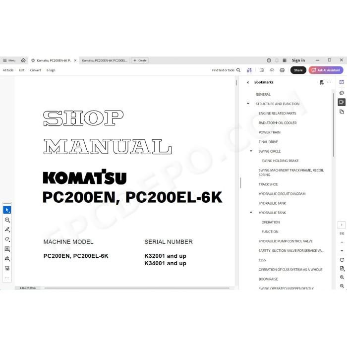
Komatsu Hydraulic Excavator PC200EN-6K, PC200EL-6K pdf workshop service manual
Serial numbers:
K30001 and up
K32001 and up
K34001 and up
Technical data, specifications, testing, adjusting, troubleshooting, electrical wiring diagrams, hydraulic schematics, assembly, removal, installation instructions and other information
MANUAL CONTENT:
GENERAL
STRUCTURE AND FUNCTION
ENGINE RELATED PARTS
RADIATOR OIL COOLER
POWER TRAIN
FINAL DRIVE
SWING CIRCLE
SWING MACHINERY TRACK FRAME, RECOIL SPRING
TRACK SHOE
HYDRAULIC CIRCUIT DIAGRAM
HYDRAULIC TANK
HYDRAULIC PUMP CONTROL VALVE
SAFETY- SUCTION VALVE FOR SERVICE VALVE
CLSS
OPERATION OF CLSS SYSTEM AS A WHOLE
BOOM RAISE
SWING OPERATED INDEPENDENTLY
COMPOUND OPERATION
BOOM OUT, STANDARD MODE RELIEF (CUTT- OFF CONTROL)
SWING MOTOR
CENTER SWIVEL JOINT
TRAVEL MOTOR
VALVE CONTROL WORK EQUIPMENT - SWING PPC VALVE
TRAVEL PPC VALVE SERVICE PPC VALVE
SAFETY LOCK VALVE
PPC ACCUMULATOR
PPC SHUTTLE TRAVEL JUNCTION VALVE
PPC SHUTTLE VALVE
TRAVEL JUNCTION VALVE
STRAIGHT- TRAVEL SYSTEM
EPC SOLENOID VALVE
HYDRAULIC CYLINDER
BOOM CYLINDER
ARM CYLINDER
BUCKET CYLINDER
OVERLOAD WARNING DEVICE
HOSE BURST PROTECTION VALVE (BOOM)
WORK EQUIPMENT ENGINE CONTROL SYSTEM
ELECTRONIC CONTROL SYSTEM
TOTAL SYSTEM DIAGRAM
MACHINE MONITOR SYSTEM
CHANGING DEFAULT WORKING MODE
TESTING AND ADJUSTING
TABLE OF JUDGEMENT STANDARD VALUE
STANDARD VALUE TABLE FOR ELECTRICAL PARTS
MEASURING ENGINE SPEED
MEASURING EXHAUST GAS COLOR
ADJUSTING VALVE CLEARANCE
MEASURING COMPRESSION PRESSURE
MEASURING BLOW- BY PRES-SURE
TESTING AND ADJUSTING FUEL INJECTION TIMING
MEASURE ENGINE OIL PRESSURE
TESTING AND ADJUSTING FAN BELT TENSION
MEASURING SPEED SENSOR
CHECKING AND ADJUSTING BELT TENSION FOR AIR CONDITIONER COMPRESSOR
TESTING AND ADJUSTING GOV-ERNOR MOTOR LEVER STROKE
TESTING CLEARANCE OF SWING CIRCLE BEARING
TESTING AND ADJUSTING TRACK SHOE TENSION
TESTING AND ADJUSTING HYDRAULIC PRESSURE IN WORK EQUIPMENT, SWING, TRAVEL CIRCUIT
TESTING AND ADJUSTING TVC VALVE OUTPUT PRESSURE (SERVO PISTON INPUT PRESSURE)
TESTING AND ADJUSTING LS VALVE OUTPUT PRESSURE (SERVO PISTON INPUT PRESSURE) AND LS DIFFERENTIAL PRESSURE
CONTROL PUMP CIRCUIT OIL PRESSURE
TESTING EPC VALVE SOLENOID VALVE OUTPUT PRESSURE
MEASURING PPC VALVE OUTPUT PRESSURE AND TESTING PPC SHUTTLE VALVE
ADJUSTING WORK EQUIPMENT, SWING PPC VALVE
TESTING TRAVEL DEVIATION
TESTING LOCATIONS CAUSING HYDRAULIC DRIFT OF WORK EQUIPMENT
MEASURING OIL LEAKAGE
RELEASING REMAINING PRESSURE IN HYDRAULIC CIRCUIT
BLEEDING AIR
TROUBLESHOOTING
POINTS TO REMEMBER WHEN TROUBLESHOOTING
SEQUENCE OF EVENTS IN TROUBLESHOOTING
PRECAUTIONS WHEN CARRYING OUT MAINTENANCE
CHECKS BEFORE TROUBLESHOOTING
CONNECTOR TYPES AND MOUNTING LOCATIONS
CONNECTION TABLE FOR CONNECTOR PIN NUMBERS
EXPLANATION OF CONTROL MACHANISM FOR ELECTRICAL SYSTEM
DISPLAY METHOD AND SPECIAL FUNCTIONS OF MONITOR PANEL
METHOD OF USING JUDGEMENT TABLE
METHOD OF USING TROUBLESHOOTING CHARTS
DETAILS OF TROUBLESHOOTING AND TROUBLESHOOTING PROCEDURE
SERVICE CODE TABLE
POINTS TO REMEMBER WHEN CARRYING OUT TROUBLE-SHOOTING OF GOVER- NOR, PUMP CONTROLLER SYSTEM
ACTION TAKEN BY CONTROLLER WHEN ABNORMALITY OCCURS AND PROBLEMS ON MACHINE
JUDGEMENT TABLE FOR GOVERNOR, PUMP GOVERNOR (GOVERNOR CONTROL SYSTEM) AND ENGINE RELATED PARTS
ELECTRICAL CIRCUIT DIAGRAM FOR E MODE
E- 1 Abnormality in governor, pump controller power source (controller LED is OFF)
E- 2 [E308] Abnormality in fuel control dial input value is displayed
E- 3 [E317] Abnormality (disconnection) in motor drive system is displayed
E- 4 [E318] Abnormality (short circuit) in motor drive system is displayed
E- 5 [E306] Abnormality in feedback potentiometer system is displayed
E- 6 [E315] Abnormality (short circuit) in battery relay output system is displayed
E- 7 [E316] Abnormality (step- out) in motor is displayed
E- 8 Engine does not start
TROUBLESHOOTING OF ENGINE SYSTEM (S MODE)
METHOD OF USING TROUBLESHOOTING CHARTS
S- 1 Starting performance is poor (starting always takes time)
S- 2 Engine does not start
S- 3 Engine does not pick up smoothly (follow- up is poor)
S- 4 Engine stops during operations
S- 5 Engine does not rotate smoothly (hunting)
S- 6 Engine lacks output (no power)
S- 7 Exhaust smoke is black (incomplete combustion)
S- 8 Oil consumption is excessive (or exhaust smoke is blue)
S- 9 Oil becomes contaminated quickly
S- 10 Fuel consumption is excessive
S- 11 Oil is in cooling water, or water spurts back, or water level goes down
S- 12 Oil pressure caution lamp lights up (drop in oil pressure)
S- 13 Oil level rises (water, fuel in oil)
S- 14 Water temperature becomes too high (overheating)
S- 15 Abnormal noise is made
S- 16 Vibration is excessive
TROUBLESHOOTING OF GOVERNOR, PUMP CONTROLLER (PUMP CONTROL SYSTEM) (C MODE)
POINTS TO REMEMBER WHEN TROUBLESHOOTING PUMP CONTROLLER SYSTEM
ACTION TAKEN BY CONTROLLER WHEN ABNORMALITY OCCURS AND PROBLEMS ON MACHINE
JUDGEMENT TABLE FOR GOVERNOR, PUMP CONTROLLER (PUMP CONTROL SYSTEM) AND HYDRAULIC RELATED PARTS
ELECTRICAL CIRCUIT DIAGRAM FOR C MODE
C- 1 Abnormality in controller power source system (controller LED is OFF)
C- 2 [E232] Short circuit in pump TVC solenoid system is displayed
C- 3 [E233] Disconnection in pump TVC solenoid system is displayed
C- 6 [E201] Short circuit in LS bypass solenoid system is displayed
C- 7 [E211] Disconnection in LS bypass solenoid system is displayed
C- 8 [E203] Short circuit in swing brake solenoid system is displayed
C- 9 [E213] Disconnection in swing brake solenoid system is displayed
C- 10 [E205] Short circuit in 2- stage relief solenoid system is displayed
C- 11 [E215] Disconnection in 2- stage relief solenoid system is displayed
C- 12 [E206] Short circuit in travel speed solenoid system is displayed
C- 15 [E222] Short circuit in LS- EPC solenoid system is displayed
C- 19 [E226] Abnormality in pressure sensor power source system is displayed
C- 20 [E227] Abnormality in engine speed sensor system is displayed
TROUBLESHOOTING OF GOVERNOR, PUMP CONTROLLER (INPUT SIGNAL SYSTEM) (F MODE)
F- 1 Swing oil pressure switch does not light up
F- 2 Travel oil pressure switch does not light up
F- 3 Boom LOWER oil pressure switch does not light up
F- 4 Boom RAISE oil pressure switch does not light up
F- 5 Arm IN oil pressure switch does not light up
F- 6 Arm OUT oil pressure switch does not light up
F- 7 Bucket CURL oil pressure switch does not light up
F- 8 Bucket DUMP oil pressure switch does not light up
F- 9 Swing lock switch does not light up
F- 10 Kerosene mode connection does not light up
F- 11 L. H. knob switch does not light up
TROUBLESHOOTING OF HYDRAULIC, MECHANICAL SYSTEM (H MODE)
TABLE OF FAILURE MODES AND CAUSES
H- 1 Speeds of all work equipment, swing, travel are slow or lack power
H- 2 There is excessive drop in engine speed, or engine stalls
H- 3 No work equipment, travel, swing move
H- 4 Abnormal noise generated (around pump)
H- 5 Auto- deceleration does not work (when PPC shuttle valve is cause)
H- 6 Fine control ability is poor or response is poor
H- 7 Boom is slow or lacks power
H- 8 Arm is slow or lacks power
H- 9 Bucket is slow or lacks power
H- 10 Work equipment (boom, arm, bucket) does not move (but travel and swing are normal)
H- 11 Excessive hydraulic drift (boom, arm, bucket)
H- 12 Excessive time lag (engine at low idling)
H- 13 Other equipment moves when single circuit is relieved
H- 14 In F/ O modes, work equipment speed is faster than specified speed
H- 15 Lack of power when pressure rises
H- 16 In compound operations, work equipment with larger load is slow
H- 17 In swing + boom RAISE, boom RAISE is slow
H- 18 In swing + travel, travel speed drops excessively
H- 19 In work equipment boom RAISE + travel, travel speed drops excessively
H- 20 Travel deviation
H- 21 Travel speed is slow
H- 22 Steering does not turn easily or lacks power
H- 23 Travel speed does not switch or is faster than specified speed
H- 24 Travel does not move (one side only)
H- 25 Does not swing
H- 26 Swing acceleration is poor or swing speed is slow
H- 27 Excessive overrun when stopping swing
H- 28 Excessive shock when stopping swing (one direction only)
H- 29 Excessive abnormal noise when stopping swing
H- 30 Excessive hydraulic drift of swing
H- 31 Swing speed is faster than specified swing speed
TROUBLESHOOTING OF MACHINE MONITOR SYSTEM (M MODE)
ACTION TAKEN BY MONITOR PANEL WHEN ABNORMALITY OCCURS AND PROBLEMS ON MACHINE
ELECTRICAL CIRCUIT DIAGRAM FOR M MODE
M- 1 [E101] Abnormality in error data is displayed [E102] Error in clock data is displayed
M- 2 [E103] Short circuit in buzzer output or contact of 24 V wiring harness with buzzer drive harness is displayed
M- 3 [E104] Air clogging detected is displayed
M- 4 [E106] Drop in engine oil pressure detected is displayd
M- 5 [E108] Engine water temperature 105° C detected is displayed
M- 6 When starting switch is turned ON, none of the lamps on the monitor panel light up for 3 seconds
M- 7 When starting switch is turned ON, monitor panel lamps all stay lighted up and do not go out
M- 8 When starting switch is turned ON, items lighted up on monitor panel are different from actual machine (model)
M- 9 When starting switch is turned ON (engine stopped), basic check items flashes
M- 10 Preheating is not being used but (preheating monitor) lights up
M- 11 When starting switch is turned ON and engine is started, basic check items flash
M- 12 When starting switch is turned ON (engine stopped), caution items, emergency items flash (battery, engine oil pressure lamps do not light up)
M- 13 When starting switch is turned ON and engine is started, caution items, emergency items flash (when there is no abnormality in engine or items to check before troubleshooting)
M- 14 When starting switch is turned ON (engine stopped), buzzer does not sound for 1 second Caution item flashes but buzzer does not sound
M- 15 No abnormality is displayed on monitor but buzzer sounds
M- 16 Night lighting on monitor panel does not light up (liquid crystal display is normal)
M- 17 Coolant temperature gauge does not rise
M- 18 Coolant temperature gauge does not give any display (none of gauge lamps light up during operation)
M- 19 Fuel level gauge always displays FULL
M- 20 Fuel level gauge does not give display
M- 21 Swing lock switch is turned ON (LOCK) but (swing lock monitor) does not light up
M- 22 Swing prolix switch is turned ON (prolix), but (swing lock monitor) does not flash
M- 23 Service meter does not advance while engine is running
M- 24 When starting switch is at OFF and time switch is pressed, time and service meter are not displayed
M- 25 Defective fuel level sensor system
M- 26 Defective coolant temperature sensor system
M- 27 Defective engine oil level sensor system
M- 28 Defective coolant level sensor system
M- 30 Wiper does not work or switch is not being used but wiper is actuated
MAINTENANCE STANDARD
ENGINE MOUNT
SWING MACHINERY SWING CIRCLE FINAL DRIVE
IDLER CARRIER ROLLER
TRACK ROLLER
TRACK SHOE CONTROL VALVE SUCTION- SAFETY VALVE
SWING MOTOR WORK EQUIPMENT, SWING PPC VALVE
TRAVEL PPC VALVE SERVICE PPC VALVE
PPC SHUTTLE VALVE, TRAVEL JUNCTION VALVE
EPC SOLENOID VALVE
CENTER SWIVEL JOINT
ARM, BOOM SAFETY VALVE
HYDRAULIC CYLINDER
WORK EQUIPMENT
DIMENSION OF WORK EQUIPMENT
Engine S6D102E-1 workshop service manual
There are no reviews for this product.