Cart
Your shopping cart is empty!
It's never too late to make things right :)


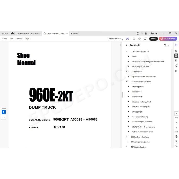
Komatsu Dump Truck 960E-2KT pdf workshop service & repair manual
Serial numbers:
A50028 - A50088
A50089 - A50090
Testing, adjusting, troubleshooting, technical data, electrical wiring diagrams, hydraulic schematics, assembly, disassembly, removal, installation instructions and other information
MANUAL CONTENT:
Index and foreword
Foreword, safety and general information
Operating instructions
Specification
Specification and technical data
Structure and functions
Steering circuit
Hoist circuit
Brake circuits
Electrical system, 24 volt
Interface module (IM)
Drive system
Cab air conditioning
Reserve engine oil system
SIBAS® IGBT rack components
Wheel motor transmission
Standard value table
Standard value table for truck
Testing and adjusting
General information
Special tool list
Steering, brake cooling and hoist hydraulic system
General information on system checkout
Steering system checkout procedures
Steering system checkout data sheet
Toe-in adjustment
Brake cooling and hoist system checkout procedures
Brake cooling and hoist system checkout data sheet
Hoist cylinder leakage test
Hydraulic system flushing procedure
Brake system
General information on system checkout
Brake circuit checkout procedure
Brake system checkout data sheet
Brake piston leakage test
Brake seal pressure test
Wet disc brake bleeding procedure
Parking brake bleeding procedure
Service brake disc wear inspection
Parking brake disc wear inspection
Brake valve bench test and adjustment
Dual relay valve bench test and adjustment
Accumulators and suspensions
Accumulator charging and storage
Bladder accumulator charging procedure
Piston accumulator charging procedure
Piston accumulator storage
Piston accumulator leak testing
Checking for improper suspension charge on operating trucks
Suspension oil change recommendations
Suspension oiling and charging procedures
Suspension pressure test
Payload meter IV
Payload meter IV software and tools
Payload meter IV system configuration
Payload meter IV software installation
Inclinometer calibration and clean truck tare
Payload meter IV checkout procedure
PLM IV system checkout data sheet
Downloading PLM IV data and possible errors
Cab air conditioning
General information
Service tools and equipment
Detecting leaks
System performance test
Checking system oil
System flushing
Installing the manifold gauge set
Recovering and recycling refrigerant
Evacuating the air conditioning system
Charging the air conditioning system
Interface module (IM)
Interface module software
Interface module checkout procedures
IGBT haul truck SIBAS® user manual, part 1
Abbreviations
Precautions
Qualified person
Customer monitor for SIBAS® 32 control units
Installing and calling the customer monitor
Installation
Communication with the SIBAS® 32 control unit
Calling up the customer monitor
Notes on operation of the customer monitor
Structure of a monitor command
Command buffer
Structure of the monitor windows
Window menu
"Window Work open"
"Window Lines open"
"Window Tile"
"Window Bars open"
"Window Set"
"Window Cascade"
"Window Close"
"Window close All"
"Window Exit"
Set Menu
"Set Port"
"Set Baudrate"
"Set String"
"Set Make"
"Set Execute"
"Set Record"
"Set DIN-Bus"
"Set TCN"
"Set Timeout"
"Set Wait"
"Set Color"
"Set Info"
"Set comment"
"Set CHAR Set"
"Set Quit"
Applic. Menu
"Applic. Func.Package"
"Applic. Connector"
"Applic. View"
"Applic. Signal"
"Applic. Observer"
"Applic. Buffer"
"Applic. Report"
"Applic. Legitimation"
"Applic. Menu"
"Applic. Traco"
"Applic. Environment"
Hardw. Menu
"Hardw. Flash"
"Hardw. Clock"
"Hardw. DSP"
"Hardw. BCD"
"Hardw. RESET"
"Hardw. Info"
"Hardw. User Flash"
"Hardw. Sys. Flash"
"Hardw. BOOT DSP"
"Hardw. Flash"
"Hardw. RESET"
"Hardw. ZR"
"Hardw. BOOT ZR"
Graphic Menu
"Graphic Load"
"Graphic Position"
"Graphic Time/Div"
"Graphic Unit/Div"
"Graphic Display"
"Graphic Color"
"Graphic Format"
IGBT haul truck SIBAS® user manual, part 2
Traco Menu
HW-Traco
SW-Traco
DAC_Traco
Events Menu
STatistics
History
LEL:Last EvL
LES:Last EvS
DLL:DC,LastL
DLS:DC,LastS
DAL:DC,All L
DAS:DC,All S
ML:Memory L
MS:Memory S
CN:Clear Norm
CA:Clear All
Test-Code
DS:Diag-Strc
User Menu
DAC_IO
Acc test
Engine_Test
X_Test_Inx
STate intern
Pedal calib
Language
OFFline-test
Variables
IV:Vehic-ID
Commands
Settings
Parameters
Temp_prot
Appendix
Background commands
Monitor commands for the central processing unit
Monitor commands for the signal processing unit
Installing ZR / DSP software
Monitor Program – Loading software into the SIBAS®
Loading software into the CPU procedure
Loading ZR software Prog. jumpers Reset
Loading the proper pgm file
Setting the system up After loading a new pgm
Troubleshooting
Fuse and circuit breaker locations
Troubleshooting by fault code, Part 1
Fault Code A001: Left front suspension pressure sensor signal high
Fault Code A002: Left front suspension pressure sensor signal low
Fault Code A003: Right front suspension pressure sensor signal high
Fault Code A004: Right front suspension pressure sensor signal low
Fault Code A005: Left rear suspension pressure sensor signal high
Fault Code A006: Left rear suspension pressure sensor signal low
Fault Code A007: Right rear suspension pressure sensor signal high
Fault Code A008: Right rear suspension pressure sensor signal low
Fault Code A009: Incline sensor signal high
Fault Code A010: Incline sensor signal low
Fault Code A011: Payload meter speed sensor signal has failed
Fault Code A013: Body up switch has failed
Fault Code A014: Payload meter checksum computation has failed
Fault Code A016: Payload meter write to flash memory has failed
Fault Code A017: Payload meter flash memory read has failed
Fault Code A018: Right rear flat suspension cylinder warning
Fault Code A019: Left rear flat suspension cylinder warning
Fault Code A022: Carryback load excessive
Fault Code A100: An open circuit breaker has been detected on a relay board
Fault Code A101: High pressure detected across an hydraulic pump filter
Fault Code A105: Fuel level sensor shorted to ground, indicating a false high fuel level
Fault Code A111: Low steering pressure warning for storage by KOMTRAX Plus
Fault Code A115: Low steering precharge pressure detected
Fault Code A117: Low brake accumulator pressure warning for storage by KOMTRAX Plus
Fault Code A118: Brake pressure is low while in brake lock
Fault Code A126: Oil level in the hydraulic tank is low
Fault Code A127: IM-furnished +5 volt output for sensors is low
Fault Code A128: IM-furnished +5 volt output for sensors is high
Fault Code A139: Low fuel warning for storage by KOMTRAX Plus and for use by A310
Troubleshooting by fault code, part 2
Fault Code A145: Hydraulic temperature sensors cause advance of engine rpm to advance level 1 for cooling of hydraulic oil
Fault Code A146: Hydraulic temperature sensors cause advance of engine rpm to advance level 2 for cooling of hydraulic oil
Fault Code A152: Starter failure
Fault Code A153: Battery voltage is low with the truck in operation
Fault Code A154: Battery charging voltage is excessive
Fault Code A155: Battery charging voltage is low
Fault Code A158: Fuel level sensor is open or shorted high, indicating a false low fuel level
Fault Code A166: Left rear hydraulic oil temperature sensor is low
Fault Code A167: Right rear hydraulic oil temperature sensor is low
Fault Code A168: Left front hydraulic oil temperature sensor is low
Fault Code A169: Right front hydraulic oil temperature sensor is low
Fault Code A170: Left rear hydraulic oil temperature sensor is high
Fault Code A171: Right rear hydraulic oil temperature sensor is high
Fault Code A172: Left front hydraulic oil temperature sensor is high
Fault Code A173: Right front hydraulic oil temperature sensor is high
Fault Code A184: J1939 data link is not connected
Fault Code A190: Auto lube control has detected an incomplete lube cycle
Fault Code A194: Left front hydraulic oil temperature is high
Fault Code A195: Right front hydraulic oil temperature is high
Fault Code A196: Left rear hydraulic oil temperature is high
Fault Code A197: Right rear hydraulic oil temperature is high
Fault Code A198: Hoist pressure 1 sensor is high
Fault Code A199: Hoist pressure 2 sensor is high
Fault Code A200: Steering pressure sensor is high
Fault Code A201: Brake pressure sensor is high
Fault Code A202: Hoist pressure 1 sensor is low
Fault Code A203: Hoist pressure 2 sensor is low
Fault Code A204: Steering pressure sensor is low
Fault Code A205: Brake pressure sensor is low
Fault Code A206: Ambient temperature sensor is high
Fault Code A207: Ambient temperature sensor is low
Troubleshooting by fault code, Part 3
Fault Code A213: Parking brake should have applied but is detected as not having applied
Fault Code A214: Parking brake should have released but is detected as not having released
Fault Code A215: Brake auto apply valve circuit is defective
Fault Code A216: An open or short to ground has been detected in the parking brake command valve circuit
Fault Code A223: Excessive engine cranking has occurred or a jump start has been attempted
Fault Code A230: Parking brake has been requested while truck still moving
Fault Code A231: The body is up while traveling or with selector in forward or neutral
Fault Code A233: Drive System Control Link is not connected
Fault Code A235: Steering accumulator is in the process of being bled down
Fault Code A236: The steering accumulator has not properly bled down after 90 seconds
Fault Code A237: The CAN/RPC connection to the display is open
Fault Code A238: Drive System and IM are reporting different park brake status
Fault Code A239: The Drive System and IM are reporting different brake lock status
Fault Code A240: The keyswitch input to the Interface Module is open
Fault Code A242: Fuel gauge within the dash display panel is defective
Fault Code A243: Engine coolant temperature gauge within the dash display panel is defective
Fault Code A244: Drive system temperature gauge within the dash display panel is defective
Fault Code A245: Hydraulic oil temperature gauge within the dash display panel is defective
Fault Code A246: Payload meter reports truck overload
Fault Code A247: Low steering pressure warning for display to operator
Fault Code A248: Status module within the dash display panel is defective
Fault Code A249: Red warning lamp within the dash display (driven by IM) is shorted
Fault Code A250: Battery voltage is low with the truck parked
Fault Code A251: Sonalert used with the dash display (driven by IM) is open or shorted to ground
Fault Code A252: Start enable output circuit is either open or shorted to ground
Fault Code A253: Steering bleed circuit is not open while running
Fault Code A256: Red warning lamp in the dash display (driven by IM) is open
Fault Code A257: Payload CAN/RPC is not connected
Fault Code A258: Steering accumulator bleed pressure switch circuit is defective
Troubleshooting by fault code, Part 4
Fault Code A260: Parking brake failure
Fault Code A261: Low brake accumulator pressure warning for display to operator
Fault Code A262: Steering bleed valve circuit open during shutdown
Fault Code A264: Parking brake relay circuit is defective
Fault Code A265: Service brake failure
Fault Code A266: Selector switch was not in park while attempting to crank engine
Fault Code A267: Parking brake was not set while attempting to crank engine
Fault Code A268: Secondary engine shutdown while cranking
Fault Code A270: Brake lock switch power supply is not on when required
Fault Code A271: Shifter not in gear
Fault Code A272: Brake lock switch power supply is not off when required
Fault Code A273: A fault has been detected in the hoist or steering pump filter pressure switch circuit
Fault Code A274: A brake setting fault has been detected
Fault Code A275: A starter has been detected as engaged without a cranking attempt
Fault Code A277: Parking brake applied while loading
Fault Code A278: Service brake applied while loading
Fault Code A279: Low steering pressure switch is defective
Fault Code A280: Steering accumulator bleeddown switch is defective
Fault Code A281: Brake lock degrade switch is defective
Fault Code A282: The number of excessive cranking counts and jump starts without the engine running has reached 7
Fault Code A283: An engine shutdown delay was aborted because the parking brake was not set
Fault Code A284: An engine shutdown delay was aborted because the secondary shutdown switch was operated
Fault Code A285: The parking brake was not set when the keyswitch was turned off
Fault Code A286: A fault was detected in the shutdown delay relay circuit
Fault Code A292: The shutdown delay relay has remained on after the latched keyswitch circuit is off
Troubleshooting by fault code, part 5
Fault Code A303: Shifter is defective
Fault Code A304: Auto lube grease level fault
Fault Code A305: Auto lube circuit is defective
Fault Code A309: No brakes applied when expected
Fault Code A310: Low fuel warning
Fault Code A311: Brake lock switch is on when it should not be
Fault Code A312: DCDC converter 12 volt circuit sensing is producing low readings
Fault Code A313: DCDC converter 12 volt circuit sensing is producing high readings
Fault Code A315: DCDC converter 12 volt circuit is low
Fault Code A316: Starter engagement has been attempted with engine running
Fault Code A317: Operation of brake auto apply valve without a detected response
Fault Code A318: Unexpected power loss to Interface Module
Fault Code A328: Drive system not powered up
Fault Code A334: Selector switch not in park when propel was either not ready or at rest
Fault Code A335: Manual/Auto Apply Pressure Fault
Fault Code A350: Overload on output 1B
Fault Code A351: Overload on output 1E
Fault Code A352: Overload on output 1H
Fault Code A353: Overload on output 1J
Fault Code A354: Overload on output 1K
Fault Code A355: Overload on output 1L
Fault Code A356: Overload on output 1M
Fault Code A357: Overload on output 1N
Fault Code A358: Overload on output 1P
Fault Code A359: Overload on output 1R
Fault Code A360: Overload on output 1S
Fault Code A361: Overload on output 1T
Fault Code A362: Overload on output 1U
Fault Code A363: Overload on output 1X
Fault Code A364: Overload on output 1Y
Fault Code A365: Overload on output 1Z
Drive system fault code table
Cab air conditioning
Reserve engine oil system
Steering system
Automatic lubrication (auto lube) system
Disassembly and assembly
General information
Special tool list
Wheels, spindles and rear axle
General precautions for tires and rims
Rim components
Removal and installation of front wheel
Removal and installation of rear wheel
Removal and installation of tires
Removal and installation of front wheel hub and spindle
Disassembly and assembly of front wheel hub and spindle
Removal and installation of wheel motor
Removal and installation of electric motor
Disassembly and assembly of wheel motor transmission
Disassembly and assembly of low speed carrier
Disassembly and assembly of high speed carrier
Removal and installation of rear axle
Removal and installation of anti-sway bar
Removal and installation of pivot pin
Pivot eye and bearing service
Brake system
Removal and installation of brake valve
Disassembly and assembly of brake valve/pedal assembly
Removal and installation of dual relay valve
Removal and installation of brake manifold
Disassembly and assembly of brake manifold
Removal and installation of brake accumulator
Disassembly and assembly of brake accumulator
Disassembly and assembly of wheel brake
Removal and installation of rear brake assembly
Removal and installation of parking brake
Disassembly and assembly of parking brake
Steering system
Removal and installation of steering control unit
Disassembly and assembly of steering control unit
Removal and installation of steering column
Removal and installation of steering wheel
Removal and installation of bleeddown manifold
Removal and installation of flow amplifier
Disassembly and assembly of flow amplifier
Removal and installation of steering cylinders and tie rod
Disassembly and assembly of steering cylinders
Removal and installation of steering/brake pump
Disassembly and assembly of steering/brake pump
Removal and installation of bladder style steering accumulators
Disassembly and assembly of bladder style steering accumulators
Removal and installation of piston style steering accumulators
Disassembly and assembly of piston accumulators
Suspensions
Removal and installation of front suspension
Minor front suspension repairs (lower bearing and seals)
Major front suspension rebuild
Removal and installation of rear suspension
Disassembly and assembly of rear suspension
Hoist circuit
Removal and installation of hoist pump
Disassembly and assembly of hoist pump
Removal and installation of hoist valve
Disassembly and assembly of hoist valve
Overcenter valve manifold service
Removal and installation of hoist pilot valve
Disassembly and assembly of hoist pilot valve
Removal and installation of hoist cylinders
Disassembly and assembly of hoist cylinders
Operator cab
Removal and installation of operator cab
Removal and installation of cab door
Disassembly and assembly of cab door
Adjustment of cab door
Removal and installation of side window glass
Removal and installation of windshield and rear window glass
Removal and installation of windshield wiper motor
Removal and installation of windshield wiper arm
Removal and installation of windshield wiper linkage
Removal and installation of operator seat
Removal and installation of passenger seat
Removal and installation of seat belts (standard seats)
Removal and installation of seat belts (optional seats)
Body and structures
Removal and installation of dump body
Removal and installation of body pads
Removal and installation of diagonal ladder/ hood and grille assembly
Removal and installation of right deck
Removal and installation of left deck
Removal and installation of fuel tank
Removal and installation of fuel gauge sender
Disassembly and assembly of fuel tank breather
Removal and installation of hydraulic tank
Cab air conditioning
Replacement of air conditioning system components
Power module
Removal and installation of power module
Exhaust tube installation
Exhaust blanket installation
Removal and installation of alternator
Removal and installation of engine
Removal and installation of radiator
Repairing the radiator
Automatic lubrication (autolube) system
Lubrication system priming
Disassembly and assembly of lubrication pump
Three phase wheel motor
General safety information
Handling the motor
Transport
Storage
Motor description
Maintenance
Safety guidelines
Maintenance intervals
Maintenance work on the installed motor
Regreasing the bearings
Applying grease to the bearings
Checking the interior of the motor for water
Disassembling the motor
Removing the coupling
Disassembling the rotor
Removing the rubber seals and the air baffles
Removing the bearing and labyrinth ring
Maintenance work
Cleaning
Stator inspection
Rotor inspection
Testing the insulation
Work on the bearings
Assembling the motor
Important general instructions
Assembling the rubber seals and the air baffles
Assembly after special repair work
Bearing installation (D-end)
Bearing installation (N-end)
Assembling the bearing shield (N-end) at the stator frame
Installing the bearing
Installing the rotor
Installing the labyrinth ring
Installing accessories (D- and N-end)
Running in the bearings
Installing the gear wheel
Installing the coupling
Assembly conditions and instructions
Repairing the motor
Replacing defective connecting leads
Repairing the stator winding insulation
Recommended consumables
Chemical cleaning agents
Rolling-contact bearing grease
Assembly/disassembly agents for bearing seat
Sealants for joining parts or gaps
Locking agents for connecting elements
Anti-corrosion agent
Assembly paste for temperature sensors
Paints for refinishing the painted parts or touching up damaged parts
Special tools
Mounting devices for inserting and withdrawing the rotor horizontally
Press for expanding the coupling
Compression devices for pressing on or for support while pressing off
Pulling units with cross beam or disk
Aids
Extraction devices
Main blower
Removing the main blower motor
Disassembling the main blower motor
Assembling the main blower motor
Installing the main blower motor
Retarding grid
Removing the grid blower motor
Disassembling the grid blower motor
Assembling the grid blower motor
Installing the grid blower motor
Removing a grid element
Control cabinet
Removing the SIBAC Inverter Module
Installing the SIBAC Inverter Module
Draining and filling the IGBT coolant system
Removing and installing the IGBT coolant pump assembly
Diagrams and drawings
Hydraulic circuit diagrams
Electrical circuit diagrams
Electrical circuit diagrams - drive system
There are no reviews for this product.