Cart
Your shopping cart is empty!
It's never too late to make things right :)


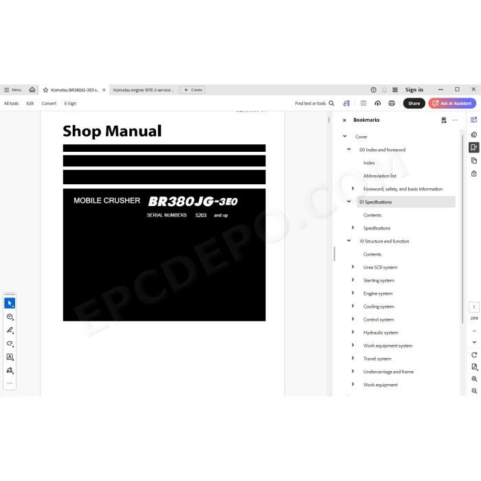
Komatsu Mobile Crusher BR380JG-3E0 pdf workshop service repair manual
Serial number 5203 and up
Specifications, technical data, testing, troubleshooting, maintenance, electrical diagrams, hydraulic schematics, adjusting, assembly, disassembly, removal, installation instructions and other information
MANUAL CONTENT:
Index and foreword
Abbreviation list
Foreword, safety, and basic information
How to read the shop manual
Safety notice for operation
Precautions to prevent fire
Action if fire occurs
Precautions when disposing of waste materials
Actions taken to meet exhaust gas regulations
Precautions for DEF
Store DEF
Precautions for handling hydraulic component
Piping - Precautions for disconnection and connection
Precautions for handling electrical component
Precautions for handling fuel system component
Precautions for handling air intake system component
Practical use of KOMTRAX
Disconnection and connection of push-pull type coupler
Precautions for disconnecting and connecting connector
Procedures for disconnecting and connecting DT connectors
Procedures for disconnecting and connecting slide lock type connectors
Procedures for disconnecting and connecting connectors with pull and release type lock
Procedures for disconnecting and connecting connectors with push and release type lock
Procedures for disconnecting and connecting connectors that require rotation of housing to release and apply lock
How to read wire code
Description of terms used in maintenance standard
Standard tightening torque table
Specifications
Specification drawing
Weight table
Table of fuel, coolant and lubricants
Structure and function
Urea SCR system
Urea SCR system component layout drawing
Urea SCR system diagram
Urea SCR system functions
Urea SCR system components
Starting system
Starting system component layout drawing
System operating lamp system
Battery disconnect switch
Engine system
Engine system component layout drawing
Engine control system
Engine automatic warm-up system
Overheat prevention system
Turbocharger protection system
Engine system component
Cooling system
Cooling system component layout drawing
Control system
Control system component layout drawing
Machine monitor system
KOMTRAX system
Control system component
Hydraulic system
Hydraulic system component layout drawing
CLSS
Pump and engine combined control system
Pump and valve control system
Hydraulic system components
Work equipment system
Work equipment system component layout drawing
Structure of valve control
Grizzly feeder semi automatic control system
Abnormal load shutdown system
Crusher jaw tip adjustment system
Work equipment system components
Crusher motor
Travel system
Travel system component layout drawing
Travel control system diagram
Travel system components
Undercarriage and frame
Undercarriage layout drawing
Work equipment
Primary conveyor
Grizzly feeder
Crusher
Vibrator
Standard value table
Standard value table for engine
Standard value table for machine
Machine posture and measuring procedure drawings for performance measurement
Testing and adjusting
Precautions before work
Related information on testing and adjusting
Tools for testing and adjusting
Sketches for testing and adjusting tools
Engine and cooling system
Testing engine speed
Testing boost pressure
Testing exhaust gas color
Testing and adjusting valve clearance
Testing compression pressure
Testing blowby pressure
Testing engine oil pressure
Testing EGR valve and VGT oil pressures
Testing fuel pressure
Testing fuel discharged volume, return rate, and leakage
Bleeding air from fuel system
Testing leakage from fuel system
Handling cylinder cutout mode operation
Handling no-injection cranking operation
Testing fan/alternator belt
Testing automatic tensioner
Writing soot correction by ash influence to engine controller
Testing SCR-related functions
Flushing DEF tank
Undercarriage and frame
Testing and adjusting track shoe tension
Hydraulic system
Releasing remaining pressure from hydraulic system
Testing and adjusting oil pressure in work equipment and travel circuits
Testing control circuit pressure
Testing and adjusting pump PC control circuit pressure
Testing and adjusting pump LS control circuit pressure
Testing solenoid valve output pressure
Testing PPC valve outlet pressure
Testing oil leakage
Bleeding air from hydraulic circuit
Procedure for adjusting mirrors
Electrical system
Setting and operating machine monitor
Start up KOMTRAX system (Machine with gateway function controller)
Stop using of KOMTRAX system (Machine with gateway function controller)
Handling voltage circuit of engine controller
Handling battery disconnect switch
Testing diode
Pm Clinic
Pm Clinic Service
Troubleshooting
Precautions before work
Information related to troubleshooting
Points to remember when performing troubleshooting
Points to remember when performing troubleshooting of urea SCR system
How to proceed in troubleshooting
Check before starting troubleshooting
Procedure for checking electrical parts
Troubleshooting procedure
Symptom of failure and troubleshooting numbers
Information described in troubleshooting table
Troubleshooting procedure of wiring harness in pressure sensor system
Connector list and layout
Connector pin numbers and wiring table
T-box and T-adapter list
Fuse location table
Precautions when cleaning and replacing KDPF (KCSF and KDOC)
Preparation of short connectors (for troubleshooting for failure codes [CA1883] and [CA3135])
Failure codes table
Troubleshooting by failure code (display of code)
Troubleshooting of electrical system (E mode)
Troubleshooting for hydraulic and mechanical system (H mode)
Troubleshooting of engine (S mode)
Disassembly and assembly
Precautions before work
Related information on disassembly and assembly
How to read this manual
Coating materials list
Special tools list
Sketches of special tools
Engine and cooling system
Removal and installation of supply pump assembly
Removal and installation of injector assembly
Removal and installation of cylinder head assembly
Removal and installation of EGR valve assembly
Removal and installation of EGR cooler assembly
Removal and installation of starting motor assembly
Removal and installation of alternator belt
Removal and installation of radiator assembly
Removal and installation of hydraulic oil cooler assembly
Removal and installation of aftercooler assembly
Removal and installation of engine and main pump assembly
Removal and installation of engine front oil seal
Removal and installation of engine rear oil seal
Removal and installation of fuel cooler assembly
Removal and installation of engine hood assembly
Removal and installation of fuel tank assembly
Removal and installation of DEF tank assembly
Removal and installation of DEF tank sensor flange assembly
Removal and installation of DEF tank sensor
Removal and installation of DEF tank strainer
Removal and installation of DEF tank filler port filter
Removal and installation of KDPF assembly
Disassembly and assembly of KDPF assembly
Removal and installation of SCR assembly
Removal and installation of KDPF and SCR assembly
Removal and installation of bracket for KDPF and SCR assembly
Removal and installation of KCCV assembly
Removal and installation of DEF mixing tube
Removal and installation of DEF injector
Removal and installation of DEF pump assembly
Removal and installation of DEF hose
Removal and installation of air cleaner assembly
Power train
Removal and installation of travel motor, final drive assembly
Disassembly and assembly of final drive assembly
Undercarriage and frame
Separation and connection of track shoe assembly
Removal and installation of sprocket
Removal and installation of idler and idler cushion assembly
Disassembly and assembly of idler assembly
Disassembly and assembly of idler cushion assembly
Disassembly and assembly of track roller assembly
Disassembly and assembly of carrier roller assembly
Hydraulic system
Removal and installation of hydraulic tank assembly
Removal and installation of main pump assembly
Removal and installation of control valve assembly
Removal and installation of crusher motor assembly
Removal and installation of lock cylinder assembly
Disassembly and assembly of lock cylinder assembly
Removal and installation of primary conveyor motor
Removal and installation of grizzly feeder motor assembly
Removal and installation of magnetic separator motor assembly
Work equipment
Removal and installation of cheek plate
Removal and installation of fixed jaw plate
Removal and installation of swing jaw plate
Removal and installation of toggle plate
Removal and installation of fixed link
Removal and installation of swing jaw assembly
Removal and installation of V-sieve and balance weight
Removal and installation of crusher assembly
Removal and installation of primary conveyor assembly
Removal and installation of belt
Replacement of primary conveyor head pulley frame
Removal and installation of crusher main bearing
Removal and installation of crusher motor and V-sieve
Removal and installation of potentiometer
Removal and installation of engine front cover
Electrical system
Removal and installation of engine controller assembly
Removal and installation of work equipment controller assembly
Removal and installation of machine monitor assembly
Removal and installation of pump swash plate sensor
Removal and installation of mass air flow and temperature sensor
Removal and installation of KCCV crankcase pressure sensor
Removal and installation of SCR temperature sensor
Removal and installation of Gateway function controller assembly
Maintenance standard
Engine and cooling system
Maintenance standard for engine mount
Maintenance standard for cooling system
Power train
Maintenance standard for final drive
Maintenance standard for sprocket
Undercarriage and frame
Maintenance standard for track frame and idler cushion
Maintenance standard for idler
Maintenance standard for track roller
Maintenance standard for carrier roller
Maintenance standard for track shoe
Maintenance standard for triple grouser shoe
Hydraulic system
Maintenance standard for hydraulic tank
Maintenance standard for main pump
Maintenance standard for LS-EPC valve
Maintenance standard for PC-EPC valve
Maintenance standard for control valve
Maintenance standard for crusher motor
Maintenance standard for solenoid valve
Maintenance standard for EPC valve
Maintenance standard for travel motor
Maintenance standard for travel PPC valve
Work equipment
Maintenance standard for primary conveyor
Maintenance standard for vibrator
Maintenance standard for conveyor lift cylinder
Maintenance standard for muck discharge conveyor lift cylinder
Maintenance standard for lock cylinder
Circuit diagrams
Hydraulic circuit diagram
Symbols used on hydraulic circuit diagram
Electrical circuit diagram
Symbols used on electrical circuit diagram
Engine SAA6D107E-3 workshop service manual
There are no reviews for this product.