Cart
Your shopping cart is empty!
It's never too late to make things right :)


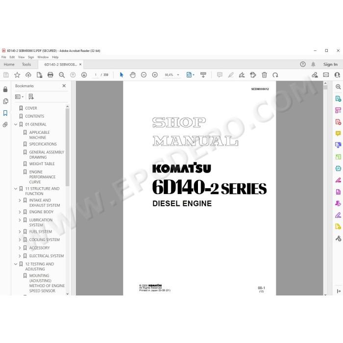
Komatsu Engine S6D140-2, SA6D140-2, SAA6D140-2, SA6D140E-2, SDA6D140E-2 series pdf workshop service & repair manual
Specifications, testing, adjusting, troubleshooting, technical data, schematics, assembly, disassembly, removal, installation instructions and other information
MANUAL CONTENT:
General
Applicable machine
Specifications
General assembly drawing
Weight table
Engine performance curve
Structure and function
Intake and exhaust system
Engine body
Lubrication system
Fuel system
Cooling system
Accessory
Electrical system
Testing and adjusting
Mounting (adjusting) method of engine speed sensor
Engine body
Fuel system
Cooling system
Fuel injection pump calibration data
Performance test
Troubleshooting
Points to remember when troubleshooting
Method of using troubleshooting charts
S-1 Starting performance is poor (starting always takes time)
S-2 Engine does not start
S-3 Engine does not pick up smoothly (follow-up is poor)
S-4 Engine stops during operations
S-5 Engine does not rotate smoothly (hunting)
S-6 Engine lacks output (no power)
S-7 Exhaust smoke is black (incomplete combustion)
S-8 Oil consumption is excessive (or exhaust smoke is blue)
S-9 Oil becomes contaminated quickly
S-10 Fuel consumption is excessive
S-11 Oil is in cooling water, or water spurts back, or water level goes down
S-12 Oil pressure caution lamp lights up (drop in oil pressure)
S-13 Oil level rises (water, fuel in oil)
S-14 Water temperature becomes too high (overheating)
S-15 Abnormal noise is made
S-16 Vibration is excessive
Testing and adjusting tool list
Testing and adjusting data
DISASSEMBLY AND ASSEMBLY
GENERAL DISASSEMBLY
Air cleaner・muffler
Starting motor
Turbocharger drain tube
Setting engine in engine overhaul stand
Corrosion resistor, air compressor suction tube
Bracket
Connector
Tension pulley assembly
Fan pulley assembly
Alternator assembly・pulley
Dipstick guide, air compressor
Fuel hose
Turbocharger
Exhaust manifold
After-cooler assembly (Intake manifold assembly)
Fuel injection tube
Fuel injection pump assembly
Tube, bracket, PTO case
Fuel filter・fuel filter bracket
Oil filter・oil regulator
Oil pan
Suction pipe, under frame
Flywheel
Rear seal
Flywheel housing
Air vent tube, spill pipe, rocker arm housing cover
Nozzle holder, inlet connector
Rocker arm
Push rod
Crosshead
Rocker arm housing
Cylinder head assembly
Vibration damper・crankshaft pulley assembly
Front support
Thermostat housing
Water pump assembly
Oil cooler assembly
Cam follower
Gear case cover
Injection pump drive gear
Camshaft
Oil pump assembly, oil pump idler gear
Main idler gear, injection pump drive shaft
Piston cooling nozzle
Piston and connecting rod assembly
Crankshaft
Cylinder liner
GENERAL ASSEMBLY
Tightening bolts by the plastic range turning angle method
Drawing of special tool
Preparatory work
Cylinder liner
Crankshaft
Piston and connecting rod assembly
Piston cooling nozzle
Main idler gear, fuel injection pump drive shaft
Oil pump idler gear, oil pump assembly
Camshaft
Fuel injection pump drive gear
Fuel injection pump drive shaft oil seal
Gear case cover
Breather
Front seal
Cam follower
Oil cooler assembly
Water pump assembly
Thermostat housing
Front support
Vibration damper, crankshaft pulley assembly
Cylinder head assembly
Crosshead
Rocker arm housing
Push rod
Rocker arm
Adjusting valve clearance
Nozzle holder, inlet connector
Rocker arm housing cover, spill pipe, air vent tube
Flywheel housing
Rear seal
Flywheel
Suction pipe
Oil pan
Oil filter assembly, oil regulator
Fuel filter assembly・fuel filter bracket
PTO case tube, bracket
Fuel injection pump assembly
Adjusting fuel injection pump
Fuel injection tube
After-cooler assembly (Intake manifold assembly)
Exhaust manifold
Turbocharger
Fuel hose
Dipstick guide, air compressor
Alternator assembly, pulley
Fan pulley assembly
Tension pulley assembly
Intake connector
Muffler bracket, air cleaner bracket
Corrosion resistor
Resetting engine in engine stand
Turbocharger drain tube
Starting motor
Air cleaner, muffler
Refilling with oil
Maintenance standard
Intake and exhaust system
Engine body
Lubrication system
Cooling system
Repair and replacement of parts
Table of special tools
Cylinder head
Grinding of fitting face ofcylinder head
Replacing valve seat insert
Pressure test
Replacing valve guide
Replacing crosshead guide
Grinding valve
Cylinder block
Replacing cam bushing
Replacing crankshaft gear
Replacing cam gear
Replacing flywheel ring gear
Replacing connecting rodsmall end bushing
Cylinder block parts
Testing and inspecting cylinder block
Correcting cylinder block top surface, counterbore
Replacing main bearing cap
There are no reviews for this product.